Chapter 4 Connecting to the Switch
When You Are Done
Follow these steps:
Step 1 | Either: |
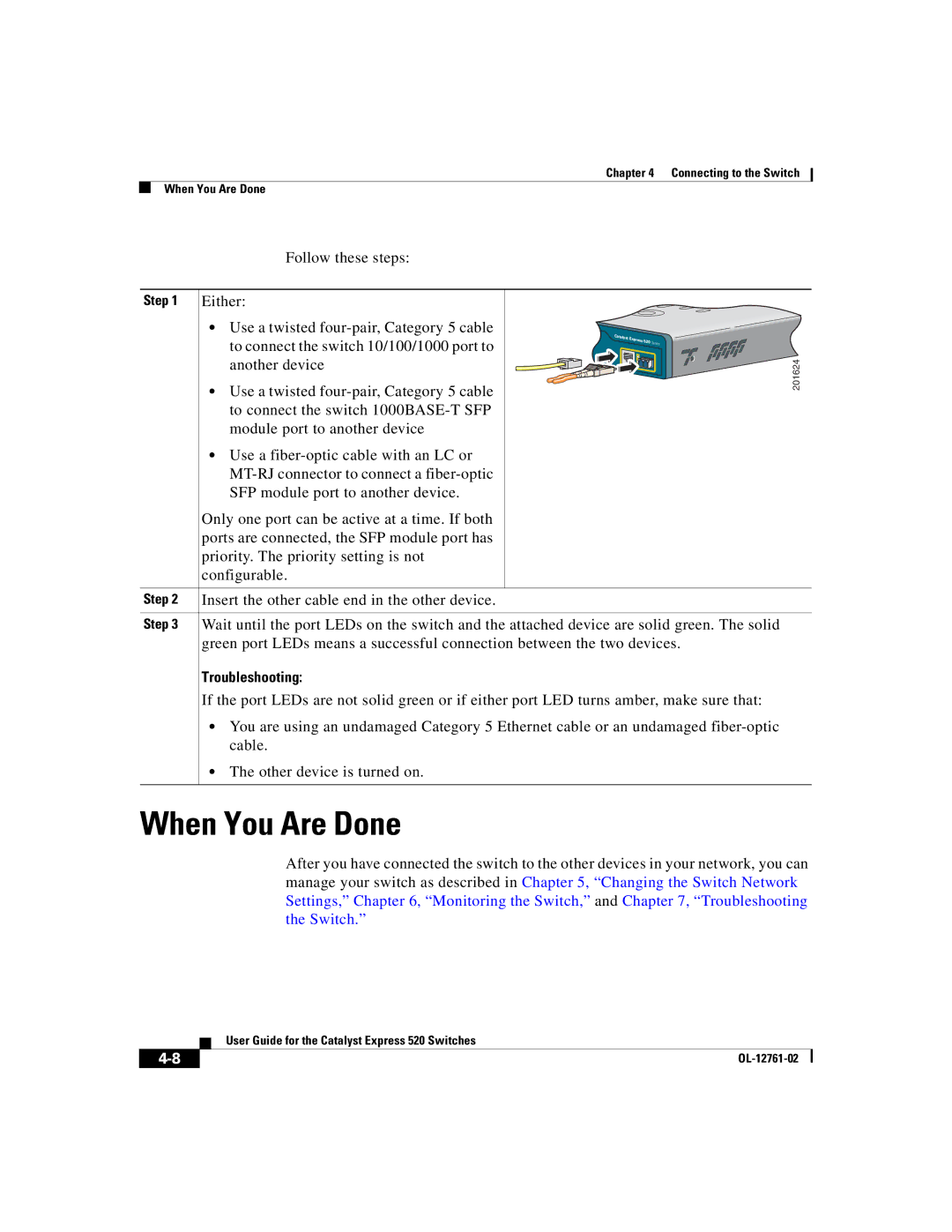
•Use a twisted
| Catalyst |
|
to connect the switch 10/100/1000 port to | Express 520 | Series |
another device | 1 |
|
|
|
• Use a twisted |
to connect the switch |
module port to another device |
• Use a |
SFP module port to another device. |
Only one port can be active at a time. If both |
ports are connected, the SFP module port has |
priority. The priority setting is not |
configurable. |
Step 2 Insert the other cable end in the other device. |
Step 3 Wait until the port LEDs on the switch and the attached device are solid green. The solid |
green port LEDs means a successful connection between the two devices. |
Troubleshooting: |
If the port LEDs are not solid green or if either port LED turns amber, make sure that: |
•You are using an undamaged Category 5 Ethernet cable or an undamaged
•The other device is turned on.
201624
When You Are Done
After you have connected the switch to the other devices in your network, you can manage your switch as described in Chapter 5, “Changing the Switch Network Settings,” Chapter 6, “Monitoring the Switch,” and Chapter 7, “Troubleshooting the Switch.”
| User Guide for the Catalyst Express 520 Switches |
|
