Chapter 2 Setting Up the Switch
Set Up the Switch (Existing Network)
Step 3
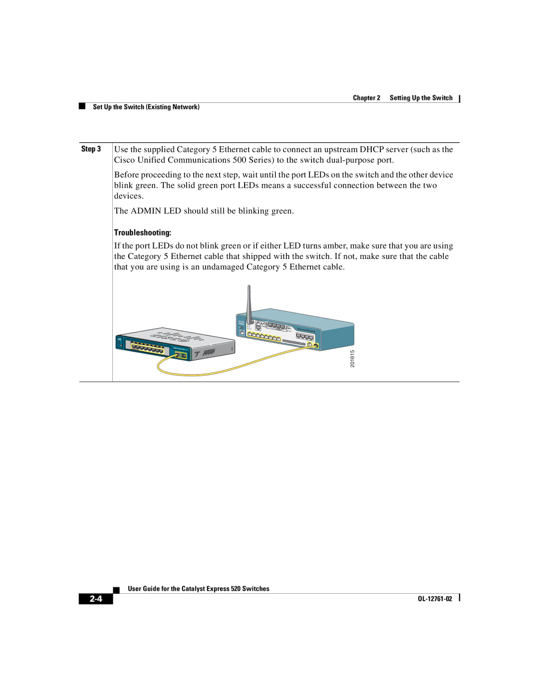
Use the supplied Category 5 Ethernet cable to connect an upstream DHCP server (such as the Cisco Unified Communications 500 Series) to the switch
Before proceeding to the next step, wait until the port LEDs on the switch and the other device blink green. The solid green port LEDs means a successful connection between the two devices.
The ADMIN LED should still be blinking green.
Troubleshooting:
If the port LEDs do not blink green or if either LED turns amber, make sure that you are using the Category 5 Ethernet cable that shipped with the switch. If not, make sure that the cable that you are using is an undamaged Category 5 Ethernet cable.
POE |
|
|
VM | Cisco |
|
WLAN |
| |
| Unified 500 | Series |
Catalyst Express |
|
|
520 Series |
| 201615 |
|
|
| User Guide for the Catalyst Express 520 Switches |