Chapter 1 Preparing for Installation
Cisco ASR 9001 Router Port Connection Guidelines
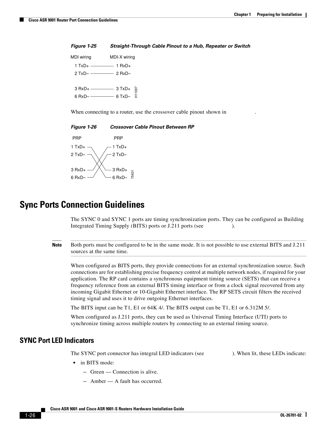
Figure
MDI wiring
1TxD+
2TxD–
3RxD+
6RxD–
1 RxD+
2 RxD–
6 TxD– | H11007 |
3 TxD+ |
|
When connecting to a router, use the crossover cable pinout shown in Figure
Figure
PRP
1TxD+
2TxD–
3RxD+
6RxD–
Crossover Cable Pinout Between RP
PRP
1 TxD+
2 TxD–
3 RxD+ | 1 |
6 RxD– | 7543 |
Sync Ports Connection Guidelines
The SYNC 0 and SYNC 1 ports are timing synchronization ports. They can be configured as Building Integrated Timing Supply (BITS) ports or J.211 ports (see Figure
Note Both ports must be configured to be in the same mode. It is not possible to use external BITS and J.211 sources at the same time.
When configured as BITS ports, they provide connections for an external synchronization source. Such connections are for establishing precise frequency control at multiple network nodes, if required for your application. The RP card contains a synchronous equipment timing source (SETS) that can receive a frequency reference from an external BITS timing interface or from a clock signal recovered from any incoming Gigabit Ethernet or
The BITS input can be T1, E1 or 64K 4/. The BITS output can be T1, E1 or 6.312M 5/.
When configured as J.211 ports, they can be used as Universal Timing Interface (UTI) ports to synchronize timing across multiple routers by connecting to an external timing source.
SYNC Port LED Indicators
The SYNC port connector has integral LED indicators (see Figure
•in BITS mode:
–Green — Connection is alive.
–Amber — A fault has occurred.
| Cisco ASR 9001 and Cisco ASR |