Chapter 1 Preparing for Installation
Site Requirement Guidelines
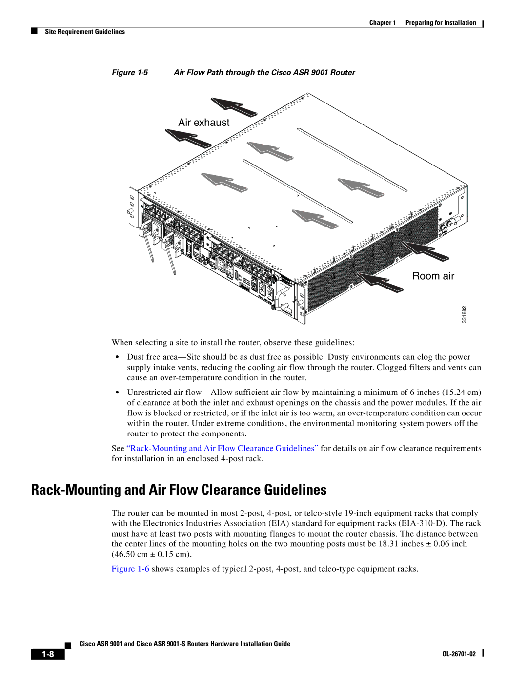
Figure 1-5 Air Flow Path through the Cisco ASR 9001 Router
Air exhaust
Room air
331882
When selecting a site to install the router, observe these guidelines:
•Dust free area—Site should be as dust free as possible. Dusty environments can clog the power supply intake vents, reducing the cooling air flow through the router. Clogged filters and vents can cause an over-temperature condition in the router.
•Unrestricted air flow—Allow sufficient air flow by maintaining a minimum of 6 inches (15.24 cm) of clearance at both the inlet and exhaust openings on the chassis and the power modules. If the air flow is blocked or restricted, or if the inlet air is too warm, an over-temperature condition can occur within the router. Under extreme conditions, the environmental monitoring system powers off the router to protect the components.
See “Rack-Mounting and Air Flow Clearance Guidelines” for details on air flow clearance requirements for installation in an enclosed 4-post rack.
Rack-Mounting and Air Flow Clearance Guidelines
The router can be mounted in most 2-post, 4-post, or telco-style 19-inch equipment racks that comply with the Electronics Industries Association (EIA) standard for equipment racks (EIA-310-D). The rack must have at least two posts with mounting flanges to mount the router chassis. The distance between the center lines of the mounting holes on the two mounting posts must be 18.31 inches ± 0.06 inch (46.50 cm ± 0.15 cm).
Figure 1-6shows examples of typical 2-post, 4-post, and telco-type equipment racks.
Cisco ASR 9001 and Cisco ASR 9001-S Routers Hardware Installation Guide

