Chapter 2 Unpacking and Installing the Chassis
Rack-Mounting the Router Chassis
The router chassis is installed in a
Cisco ASR 9001 Router chassis.
In a
The PID of the rack mounting kit for Cisco ASR 9001 Router and Cisco ASR
Verifying Rack Dimensions
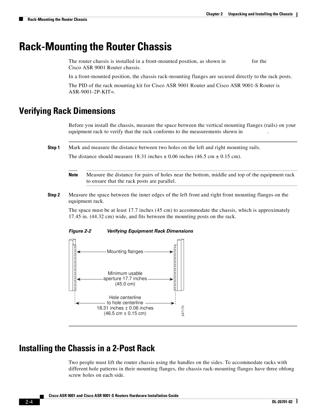
Before you install the chassis, measure the space between the vertical mounting flanges (rails) on your equipment rack to verify that the rack conforms to the measurements shown in Figure
Step 1 Mark and measure the distance between two holes on the left and right mounting rails.
The distance should measure 18.31 inches ± 0.06 inches (46.5 cm ± 0.15 cm).
Note Measure the distance for pairs of holes near the bottom, middle and top of the equipment rack to ensure that the rack posts are parallel.
Step 2 Measure the space between the inner edges of the left front and right front mounting flanges on the equipment rack.
The space must be at least 17.7 inches (45 cm) to accommodate the chassis, which is approximately 17.45 in. (44.32 cm) wide, and fits between the mounting posts on the rack.
Figure 2-2 Verifying Equipment Rack Dimensions
![]()
![]() Mounting flanges
Mounting flanges ![]()
![]()
Minimum usable
![]()
![]() aperture 17.7 inches
aperture 17.7 inches ![]()
![]()
(45.0 cm)
Hole centerline
![]() to hole centerline
to hole centerline ![]()
18.31inches ± 0.06 inches (46.5 cm ± 0.15 cm)
247170
Installing the Chassis in a 2-Post Rack
Two people must lift the router chassis using the handles on the sides. To accommodate racks with different hole patterns in their mounting flanges, the chassis
Cisco ASR 9001 and Cisco ASR
|
| |
|