Chapter 4 Troubleshooting the Installation
Troubleshooting the Power Subsystem
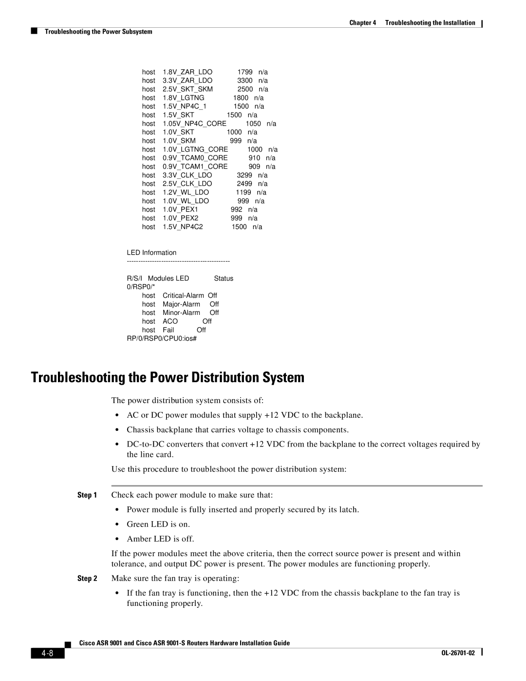
| host | 1.8V_ZAR_LDO | 1799 | n/a |
| host | 3.3V_ZAR_LDO | 3300 | n/a |
| host | 2.5V_SKT_SKM | 2500 | n/a |
| host | 1.8V_LGTNG | 1800 | n/a |
| host | 1.5V_NP4C_1 | 1500 | n/a |
| host | 1.5V_SKT | 1500 | n/a |
| host | 1.05V_NP4C_CORE | 1050 | n/a |
| host | 1.0V_SKT | 1000 | n/a |
| host | 1.0V_SKM | 999 | n/a |
| host | 1.0V_LGTNG_CORE | 1000 | n/a |
| host | 0.9V_TCAM0_CORE | 910 | n/a |
| host | 0.9V_TCAM1_CORE | 909 | n/a |
| host | 3.3V_CLK_LDO | 3299 | n/a |
| host | 2.5V_CLK_LDO | 2499 | n/a |
| host | 1.2V_WL_LDO | 1199 | n/a |
| host | 1.0V_WL_LDO | 999 | n/a |
| host | 1.0V_PEX1 | 992 | n/a |
| host | 1.0V_PEX2 | 999 | n/a |
| host | 1.5V_NP4C2 | 1500 | n/a |
LED Information |
|
|
| |
| ||||
R/S/I | Modules | LED | Status |
|
0/RSP0/* |
|
|
|
|
| host | Off |
| |
| host | Off |
| |
| host | Off |
| |
| host | ACO | Off |
|
| host | Fail | Off |
|
RP/0/RSP0/CPU0:ios#
Troubleshooting the Power Distribution System
The power distribution system consists of:
•AC or DC power modules that supply +12 VDC to the backplane.
•Chassis backplane that carries voltage to chassis components.
•
Use this procedure to troubleshoot the power distribution system:
Step 1 Check each power module to make sure that:
•Power module is fully inserted and properly secured by its latch.
•Green LED is on.
•Amber LED is off.
If the power modules meet the above criteria, then the correct source power is present and within tolerance, and output DC power is present. The power modules are functioning properly.
Step 2 Make sure the fan tray is operating:
•If the fan tray is functioning, then the +12 VDC from the chassis backplane to the fan tray is functioning properly.
Cisco ASR 9001 and Cisco ASR
|
| |
|