Chapter 4 Troubleshooting the Installation
Troubleshooting the Route Processor Subsystem
| Table 4-3 | RP Discrete LED Display Definitions (continued) |
| | | | | |
Indicator (Label) | | LED | | Color | Description |
| | | | | |
STATUS | | Bi-color | | Amber | Fan tray power ON state. |
(Fan tray) | | | | | |
| | | Green | Fan tray fully functional. |
| | | | | |
| | | | Red | Fan failure condition. |
| | | | | |
Ethernet Ports and Status LEDs
The RP has two 8-pin media-dependent interface (MDI) RJ-45 Management LAN ports for 10 Mbps, 100 Mbps, and 1000Mbps Ethernet connections. These ports are labeled MGT LAN 0 and MGT LAN 1.
The transmission speed of the Ethernet port is not user-configurable. You set the speed through an auto-sensing scheme on the RP, the speed is determined by the network to which the Ethernet port is connected. However, even at an auto-sensed data transmission rate of 100 Mbps, the Ethernet port can only provide a usable bandwidth of substantially less than 100 Mbps. You can expect a maximum usable bandwidth of approximately 12 Mbps when using an Ethernet connection.
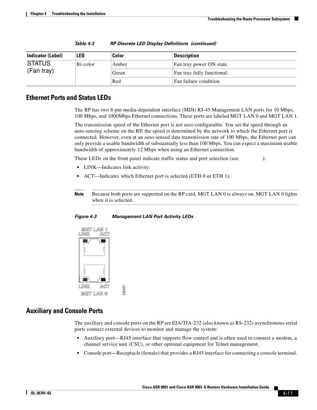
These LEDs on the front panel indicate traffic status and port selection (see Figure 4-3):
•LINK—Indicates link activity.
•ACT—Indicates which Ethernet port is selected (ETH 0 or ETH 1).
Note Because both ports are supported on the RP card, MGT LAN 0 is always on. MGT LAN 0 lights when it is selected.
Figure 4-3 Management LAN Port Activity LEDs
332427
Auxiliary and Console Ports
The auxiliary and console ports on the RP are EIA/TIA-232 (also known as RS-232) asynchronous serial ports connect external devices to monitor and manage the system:
•Auxiliary port—RJ45 interface that supports flow control and is often used to connect a modem, a channel service unit (CSU), or other optional equipment for Telnet management.
•Console port—Receptacle (female) that provides a RJ45 interface for connecting a console terminal.
| | Cisco ASR 9001 and Cisco ASR 9001-S Routers Hardware Installation Guide | | |
| | |
| OL-26701-02 | | | 4-11 | |
| | | |