Chapter 4 Troubleshooting the Installation
Troubleshooting the Route Processor Subsystem
RP Front Panel Indicators
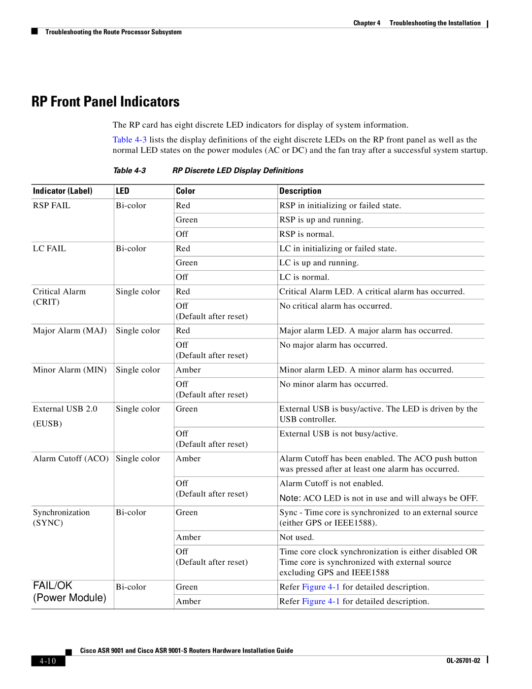
The RP card has eight discrete LED indicators for display of system information.
Table
|
|
|
| Table | RP Discrete LED Display Definitions | |||||
|
|
|
|
|
|
|
| |||
| Indicator (Label) |
| LED |
| Color | Description | ||||
|
|
|
|
|
|
|
| |||
| RSP FAIL |
|
| Red | RSP in initializing or failed state. | |||||
|
|
|
|
|
|
|
|
|
| |
|
|
|
|
|
|
| Green | RSP is up and running. | ||
|
|
|
|
|
|
|
|
|
| |
|
|
|
|
|
|
| Off | RSP is normal. | ||
|
|
|
|
|
|
|
| |||
| LC FAIL |
|
| Red | LC in initializing or failed state. | |||||
|
|
|
|
|
|
|
|
|
| |
|
|
|
|
|
|
| Green | LC is up and running. | ||
|
|
|
|
|
|
|
|
|
| |
|
|
|
|
|
|
| Off | LC is normal. | ||
|
|
|
|
|
|
|
| |||
| Critical Alarm |
| Single color |
| Red | Critical Alarm LED. A critical alarm has occurred. | ||||
| (CRIT) |
|
|
|
|
|
|
| ||
|
|
|
| Off | No critical alarm has occurred. | |||||
|
|
|
|
|
|
| ||||
|
|
|
|
|
|
| (Default after reset) |
|
|
|
|
|
|
|
|
|
|
| |||
| Major Alarm (MAJ) |
| Single color |
| Red | Major alarm LED. A major alarm has occurred. | ||||
|
|
|
|
|
|
|
|
|
| |
|
|
|
|
|
|
| Off | No major alarm has occurred. | ||
|
|
|
|
|
|
| (Default after reset) |
|
|
|
|
|
|
|
|
|
|
| |||
| Minor Alarm (MIN) |
| Single color |
| Amber | Minor alarm LED. A minor alarm has occurred. | ||||
|
|
|
|
|
|
|
|
|
| |
|
|
|
|
|
|
| Off | No minor alarm has occurred. | ||
|
|
|
|
|
|
| (Default after reset) |
|
|
|
|
|
|
|
|
|
|
| |||
| External USB 2.0 |
| Single color |
| Green | External USB is busy/active. The LED is driven by the | ||||
| (EUSB) |
|
|
|
| USB controller. | ||||
|
|
|
|
|
|
|
| |||
|
|
|
|
|
|
| Off | External USB is not busy/active. | ||
|
|
|
|
|
|
| (Default after reset) |
|
|
|
|
|
|
|
|
|
|
| |||
| Alarm Cutoff (ACO) |
| Single color |
| Amber | Alarm Cutoff has been enabled. The ACO push button | ||||
|
|
|
|
|
|
|
| was pressed after at least one alarm has occurred. | ||
|
|
|
|
|
|
|
|
|
| |
|
|
|
|
|
|
| Off | Alarm Cutoff is not enabled. | ||
|
|
|
|
|
|
| (Default after reset) | Note: ACO LED is not in use and will always be OFF. | ||
|
|
|
|
|
|
|
| |||
|
|
|
|
|
|
|
| |||
| Synchronization |
|
| Green | Sync - Time core is synchronized to an external source | |||||
| (SYNC) |
|
|
|
| (either GPS or IEEE1588). | ||||
|
|
|
|
|
|
|
|
|
| |
|
|
|
|
|
|
| Amber | Not used. | ||
|
|
|
|
|
|
|
|
|
| |
|
|
|
|
|
|
| Off | Time core clock synchronization is either disabled OR | ||
|
|
|
|
|
|
| (Default after reset) | Time core is synchronized with external source | ||
|
|
|
|
|
|
|
| excluding GPS and IEEE1588 | ||
|
|
|
|
|
|
|
| |||
| FAIL/OK |
|
| Green | Refer Figure | |||||
| (Power Module) |
|
|
|
|
|
| |||
|
|
|
| Amber | Refer Figure | |||||
|
|
|
|
|
|
|
| |||
|
|
| Cisco ASR 9001 and Cisco ASR | |||||||
|
|
| ||||||||
|
|
|
|
|
|
|
|
|
|
|
|
|
|
|
|
|
|
|
| ||
|
|
|
|
|
|
|
| |||