Cisco Systems, Inc
Page
Preface Objective
Memory
Installing the Cisco 880G for 3.7G HSPA+/3.5G Hspa ISRs
Initial Configuration of the Wireless Access Point
Power Supply A-22
OL-27407-01
Preface
Chapter Name Description
Warnung Wichtige Sicherheitshinweise
Bewaar Deze Instructies
Aviso Instruções Importantes DE Segurança
Avvertenza Importanti Istruzioni Sulla Sicurezza
Page
GEM Disse Anvisninger
Xiii
Xiv
Page
Related Documentation
Xvii
Xviii
General Description
Cisco 812 Series
A P T E R
This section contains the following
Cisco 812 ISR
3G LED
3G diversity antenna WiFi LED 3G main antenna
Cisco 812 ISR supports the following hardware features
Hardware Features
Platform Features
LEDs
Antenna
Rssi
Color Description
2describes the WiFi LED for the Cisco 812 ISR
Following are power adapters supported in the Cisco 812 ISR
Power Supply
AC Power Adapter
Memory
C812G-CIFI-S-A-K9
SKU Information
C812G-CIFI-V-A-K9
Cisco 819 Series
Wlan LED
Cisco 819HG Integrated Services Router
7shows the front panel details of the Cisco 819HG ISR
8shows the front panel details of the Cisco 819HGW ISR
SKU ID
Cisco Integrated Services Router Hardware Installation Guide
Support Description
WiFi External Antenna
Frequency Band Description
Mode
HSPA+/HSPA
Rebranding of C8xx-B and EHWIC-3G-EVDO-B
MB Dram
Platform Features for Cisco 819 ISRs
Yes
GB Dram
Yes Tftp support with Ethernet WAN Interface Warm reload
Snmp
Reset Button
Power Switch
Antennas
SYS
GPS
ACT
Wwan
Wlan LED
4G LTE LED Descriptions
SIM
Embedded 4G LTE Modem
Embedded 3G Modem
SIM Card
Two Internal SIM Card Slots
3G-ANTM-OUT-OM
Supported Cisco Antennas and Cables
3G-ANTM-OUT-LP
3G-ACC-OUT-LA
AIR-ANT2430V-R
AIR-ANTM2050D-R
AIR-ANT5140V-R
AIR-ANT2440NV-R
Maximum Gain Cisco Part Number Description Frequency Ranges
AIR-CAB020LL-R
AIR-CAB005LL-R
AIR-CAB050LL-R
Maximum Insertion
4G-CAB-ULL-20
Serial Port
20 ft 6 m 700 to 2600 MHz Black Yes
4G-CAB-ULL-50
10 12-in-1 Serial Port
DC Power Adapters
Cisco Part Number Accessory
Accessories
Railway Power Adapters
Cisco 860 Series ISRs
General Description
11 Front Panel of the Cisco 860 Series Wireless ISR
Interfaces
Cisco 860VAE Series ISRs
IOS Images
Model Interfaces
14shows the back panel details of the Cisco 866VAE ISR
Feature
Model-Specific Features
C866VAE-W-E C867VAE-W-A C867VAE-W-E
Isdn Pots
Interface Connector
Common Features
External Interfaces
Port
LED Indicators for LAN Ports
LED Indicators
USB Interface
Port LED Color Description
LED indicators
LED Indicators on Front Panel
LED Color LED Activity Description
Cisco 880 Series ISRs
Cisco 880 Series Data Routers
Isdn
18 Front Panel of the Cisco 880 Series Wireless Data Router
20 Back Panel of the Cisco 887VA and 887VA-M Router
Primary WAN port-VDSL/ADSL over Reset button
Cisco 881 Srst and Cisco 888 Srst
Cisco 880 Series Voice and Data Routers
LEDs USB port
23 Back Panel of the Cisco C881SRST-W Voice Router
24 Back Panel of the Cisco C888SRST-W Voice Router
Cisco 881-V, Cisco 887VA-V, and Cisco 887VA-V-W
LEDs USB port
Flexible Complexity Medium Complexity High Complexity
C881-V C887VA-V C887VA-V-W
27shows the back panel for the Cisco 881-V router
PoE power connector optional
Cisco 887VA-WD
Cisco 880 Series with Embedded Wlan Antennas
29 Back Panel of the C887VA-WD-A-K9 and C887VA-WD-E-K9 ISRs
C881WD
C881GW-S/V-A-K9 ISRs
C881G-B/S/V-K9 ISRs
HSPA+ Versions of the Fixed-Platform ISRs
C881G-U-K9 ISRs
Hardware Description
Cisco C881 Router
FAN
WAN
32 Front Panel of the Cisco C881 Router
33shows the back panel of the Cisco C881 Router
Cisco C886VA Router
Cisco C886VAJ Router
Primary WAN port-VDSL/ADSL over On/Off switch
USB port Reset button
37shows the back panel of the Cisco C886VAJ Router
Cisco C887VA Router
39shows the back panel of the Cisco C887VA Router
Cisco C887VAM Router
Cisco 891, Cisco 892, and Cisco 892F
Cisco 890 Series ISRs
LEDs USB ports
42 Front Panel of the Cisco 890 Series Wireless ISR
43 Back Panel of the Cisco 892-W Router
SFP port SFP LEDs
Cisco 892FSP, Cisco 896VA, Cisco 897VA, and Cisco 898EA
45shows the back panel of the Cisco 892FSP router
47shows the back panel of the Cisco 896VA router
49shows the back panel of the Cisco 897VA router
51shows the front panel of the Cisco 897VAM router
54shows the back panel of the Cisco 897VAMW router
55shows the back panel of the Cisco 898EA router
Port GE or 1-port SFP
PoE PoE ports
57shows the front panel of the Cisco C891F Router
Cisco C891F Router
Cisco C891FW Router
Primary WAN port-GE WAN On/Off switch
Back up WAN port-FE WAN Console / Auxiliary port
SFP
Product Overview Cisco C891 Series ISRs
Back up WAN port-FE Serial port-Console or auxiliary
Hardware Features
Kensington Lock
Reset Button
Cisco 860VAE Routers-Custom Configuration File
OL-27407-01
LEDs
Color Description Series
VPN
Wlan Link
Green On-VPN is connected All models
PPP3
3G RSSI10
3G8 WWAN9
3G CDMA12
Srst
Activity Description
Activity
GE Mode
Color Activity Description
Models Flash Memory Storage
Memory
Flash Memory
Main Memory
USB Port
Models
Expandability
Fan
Power Supply
Power over Ethernet Module
Throughput Mode Antenna
Wireless LAN Connectivity
3G Cellular Data WAN Connectivity
Maximum Data Radio Module Platform
Supported Cisco Radio Antennas
Throughput1 Mode Antenna
Cisco Part Number Antenna Type Maximum Gain Description
AIR-ANTM4050V-R
Small Form-Factor Pluggable Port
Feature Summary
Feature Description Series
RTC
FXS19/DID20
SRST17
Feature Description Series
Installing the Cisco 812 ISR
Installing the Router
Items Shipped with your PoE+ Splitter
Installing the Cisco PoE+ Splitter
Items Shipped with your Router
Screws
Placement of the Power Cord Lock onto the Power Cord
Power cord connector Power cord lock
To lock into the T-rail as shown in Figure
Remove one ceiling tile to gain access
Installing the SIM Card
Accessing the SIM Card
SIM Access Panel
Installing the 3G Antenna
Mounting Hardware,
Mounting the Cisco 812 ISR
Mounting Bracket
Mounting Hardware
Ceiling Grip Clips
10 Universal Bracket Installed on the Cisco 812 ISR
11shows a ceiling grid clip
Additional Adapters for Channel and Beam Ceiling Rails
12 T-Rail, Channel, and Beam Ceiling Rail Types
Mounting the Cisco 812 ISR Below a Suspended Ceiling
Installing the Router Installing the Cisco 810 ISR
14 Suspended Ceiling Mounting Details
Mounting the Cisco 812 ISR on a Hard Ceiling or a Wall
15 Universal Mounting Bracket Details
Mounting the Cisco 812 ISR to a Network or Electrical Box
16 Routing the Ethernet and Power Cables
Grounding the Cisco 812 ISR
17 Connecting the Ring Lug onto the Grounding Point
Installing the Cisco 819 ISR
Equipment, Tools, and Connections
Additional Items
Items Shipped with your Router
Connections
Ethernet Devices
Installing the Router
Replace the panel and the screws
Accessing the SIM Card
Installing a WiFi External Antenna
Installing Antennas
Mounting on a Wall
Installing on a Table
21 Attaching the Standard Brackets
22 Installing the Router to the Wall
Installing a DIN Rail
Space between the latch and hook
Turn the router sideways so that the antenna is at the top
25 Cisco 819 ISR Installed with the DIN Rail
26 Configurable Low Profile DIN Mount standard configuration
27 Low Profile DIN Mount Configuration
Configuring the Mount
Attaching the mount to the router
Ring terminal
Installing the Router Ground Connection
Ring Power cord lock
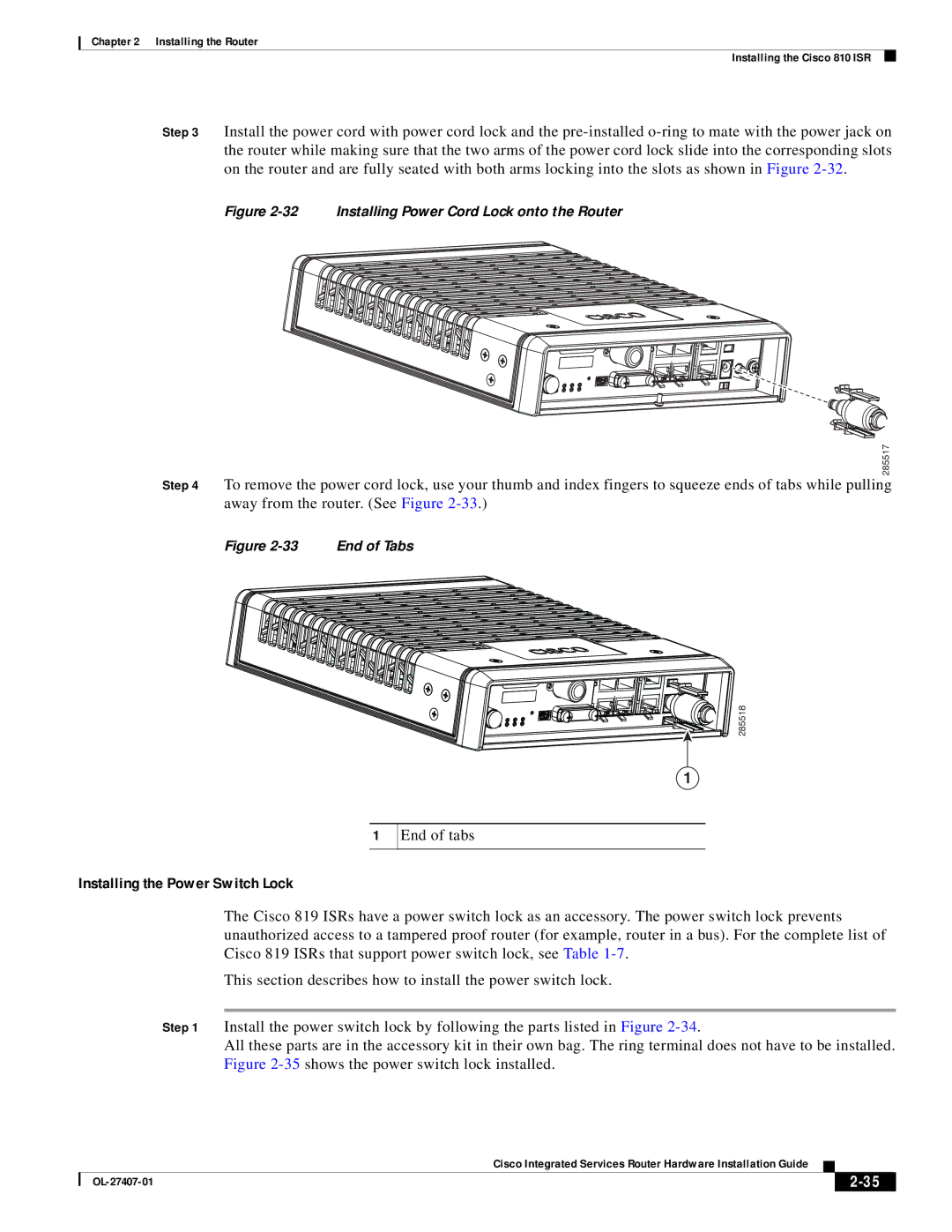
Installing the Power Cord Retention Lock
End of tabs
Installing the Power Switch Lock
34 Installing Power Switch Lock
36 DC Power Supply Wall-Mounting Features
Mounting the DC Power Supply
Statement
No user-serviceable parts inside. Do not open. Statement
Indoors. Statement
Cisco 860VAE Series Routers
Equipment, Tools, and Connections
Additional Items
Ethernet Devices
Installing the Cisco 860, 880, and 890 Series Routers
Connections
Mounting on a Wall
Installing on a Table
37 Wall-mount Holes on the Underside of the Router
38 Router Mounted on the Wall
Installing the Fips Cover
Installing the Router Ground Connection
Remove the four mounting screws of the top cover
Install the left-side Fips cover, as shown in detail a
Secure the Fips cover with two mounting screws
Installing Antennas for Cisco 890 Series
40 Attaching Antennas to the Router
41 Antennas Oriented Vertically Up
42 Antennas Oriented Vertically Down
Screws
Installing Cisco 890 Series in a Rack
272484
Installing the C881GW-S/V-A-K9 ISR
Installing the C881G-B/S/V-K9 ISR
Installing the C881G-U-K9 ISR
Installing Antennas
SIM Card Installation
Installing the Cisco 880G for 3.7G HSPA+/3.5G Hspa ISRs
Preparing to Connect the Router
Connecting the Router
Preventing Damage to the Router
Connecting a PC, Server, or Workstation
Connecting to an Ethernet Switch
Connecting an External Ethernet Switch
Connecting a Terminal or PC to the Console Port
Connecting a Terminal or PC to the Console Port
Connecting the AC Adapter
Connecting a Modem to the Console Port
DC Power Supply PWR1-20W-12VDC and PWR1-20W-24VDC
Connecting the DC Adapter
LEDs to Check Normal Patterns
Verifying Connections
Connecting the Router Cisco 860, 880, 890 Series
Safety Warnings
Preparing to Connect the Router
Preventing Damage to the Router
Connecting a PC, Server, or Workstation
Connecting a Phone
Connecting a Phone
Connecting an External Ethernet Switch
10 Connecting to Your Service Provider Through the V.92 port
Connecting the V.92 modem Port
Terminal Emulator Settings
Connecting a Terminal or PC to the Console Port
12 Connecting a Modem to the Aux Port
Connecting a Modem to the Auxiliary Port
Connecting the 3G Card
13 Inserting the 3G Card
Pins on the locking bracket for alignment
3G card Notch on the 3G card Locking bracket
15 Installing the Locking Bracket
16 Closing the Locking Bracket
Close the locking bracket, as shown in Figure
Antenna connector receptacle1
Antenna on a cradle Antenna Ssmb connector
Description SKUs Supported
20 Locating the Phillips Screw
Installing the 3G Adapter for Extended Cable/Antenna
Hooks aligned and inserted into the router
Locate the hooks on the adapter as shown in Figure
23 Attaching the Adapter
24 Adapter Connected to 3G Card and Router Chassis
Inches 66 dB 2100
Connecting a Data BRI Port
3G-ACC-TS9-TNC
Inches 62 dB 2100
25 Connecting the Data BRI Port to the Isdn Line
26 Connecting the FE WAN Port
Connecting an FE Line to an FE WAN Port
Connecting an xDSL Line
Connecting a GE Line to an GE WAN Port
OL-23125-02
28 Primary Protection Device Location
Connecting Power over Ethernet
120 VAC, 20 a U.S VAC, 16 to 20 a international. Statement
Connecting the AC Adapter
31 Connecting the AC Adapter
VDC plug Power adapter-12 VDC Power cord AC plug
Pin
VDC plug Power adapter-12 VDC Power Adapter Cord AC Plug
NC1
+12
34 Securing the Power Cord
Power lock clip Power adapter Power cord AC plug
Connecting an FXS Line
36shows an FXS line connection
Connecting an FXO Line
37 Connecting an FXO Line
Connecting a Voice Isdn BRI Line
38shows a voice BRI line connection
117722
Verifying Connections
LAN
Off when the device is powered off or when the GE WAN
On when the GE WAN interface is up
Blinking when there is GE WAN activity traffic in either
OL-23125-02
Cisco IOS CLI
Setup Command Facility
Verifying the Initial Configuration
Cisco Configuration Professional Express
Cisco IOS CLI
Press Return. The following message is displayed
Username username privilege 15 secret 0 password
Following message is displayed
Setup Command Facility
Enter interface name used to connect to
Enter a hostname for the router this example uses Router
Configuration is displayed
Verifying the Initial Configuration
Initial Configuration of the Wireless Access Point
OL-23125-02
Router Specifications
Technical Specifications
C812G-CIFI+7-E-K9
Description 3G only 3G + WiFi Physical Characteristics
C812G-CIFI+7-N-K9
C812G+7-K9
Radio Immunity EN301 489-1, EN 301 489-7, and EN301
Description 3G only 3G + WiFi
Embedded WiFi Antenna
SKUs Mtbf hours
Mean Time Between Failure Ground Benign Environment
Table A-3 Cisco 819 ISR Specifications
Table A-3
Martek Railway Power Adapters2
Table A-4
C819G+7-K9
Supported Power Adapters
C819G-B-K9
Range 4G LTE SKUs 3GSKUs
Range
WiFi SKUs
C819HG-B-K9
C819HG-S-K9
C819HGW-S-A-K9
Range 4G LTE SKUs 3G SKUs 3G + WiFi SKUs
C819HG-B-K9 C819HGW-V-A-K9
C819HG-S-K9 C819HGW+7-E-K9
This sections contains the following
Router Specifications
All Models Except Cisco 860VAE Series
Description Cisco 860VAE series Physical Dimensions
Design Specification
Router Power Adapter
Inline Power-over-Ethernet Adapter
PWR-30W-AC
Cisco 860VAE Series
AC Adapter
Description Cisco 860VAE series
Description Specification
Enclosure X 9 x 1.75 in. W x D x H
Sound Pressure Convection cooled, no fan
Cisco 870 Series
Description Design Specification Physical Dimensions
Optional external Inline PoE adapter Specifications
Description Design Specification
Power delivered via pins 4,5,7
Cisco 880 Series
External Power Supply
Wireless models H x W x D
Router Power Specifications
Operating temperature
Cisco 880VA Series
Cisco 880G Series 3G Wireless Integrated Services Router
Maximum output power 80W Output voltage, external 48 VDC
Power Supply
Wireless models
Cisco 890 Series
Wireless Access Point
Power Supply
Power Supply Unit Volt
30 W Ampere 60 W
FE and GE Port Pinouts
GE Signal
Pin Function
Pin LAN and WAN
VDSL2 Port Connector Pinouts
Console and Auxiliary Port Connector Pinouts
FXS and FXO Port Connector Pinouts
Port Connector Pinouts
ADSL2+ Port Connector Pinouts
Shdsl Port Connector Pinouts
RJ-11 Pin
TXP
Data BRI Port Connector Pinouts
RXP
TXN
Isdn BRI NT/TE Card NT Interface TE Interface
SFP Port Connector Pinouts
Voice Isdn BRI Interface Pin Numbers and Functions
Ethernet Cable Specifications
Cable Specifications
Maximum Cable Length
Type Category