Installation Operation Maintenance
Series 1 Water-CooledW1 and
Air-CooledModels A1 with TIC Control
Troubleshooting
Date Manual Number UGH016/0500 Serial numbers
Model numbers Power specifications Amps Volts
Phase Cycle
DESCRIPTION
TABLE OF CONTENTS
INTRODUCTION
PARTS AND DIAGRAMS . . . . . . . . . . . .P/D-1
MAINTENANCE
TROUBLESHOOTING
TABLE OF CONTENTS
How the guide is organized
INTRODUCTION
Purpose of the User Guide
Your responsibilities as a user
YOUR RESPONSIBILITY AS A USER
PURPOSE OF THE USER GUIDE
HOW THE GUIDE IS ORGANIZED
CAUTION Ventilation hazard
WARNING Electrical hazard
CAUTION Hot Surfaces
READ THIS SO NO ONE GETS HURT
Page
DESCRIPTION
WHAT IS THE PORTABLE CHILLER?
LIMITATIONS
TYPICAL APPLICATIONS
Temperature
Cooling load
DESCRIPTION
HOW IT WORKS WATER-COOLED PORTABLE CHILLER
Process circulation
WATER-COOLED
Refrigerant circulation
HOW IT WORKS
CONT’D
HOW IT WORKS AIR-COOLED PORTABLE CHILLER
DESCRIPTION
DESCRIPTION
HOW IT WORKS
AIR-COOLED PORTABLE CHILLER
Water-cooledModels
CHILLER FEATURES
PORTABLE
PORTABLE CHILLER FEATURES
Air-cooledModels
Dimensions in mm
SPECIFICATIONS
2-10
Weight lb kg
DESCRIPTION
Dimensions in mm
Weight lb kg
MODEL
60 HZ PUMP PERFORMANCE CURVES
PUMP CURVES
2-12
50 HZ PUMP PERFORMANCE CURVES
INSTALLATION
UNPACKING THE BOXES
CAUTION Lifting hazard
CAUTION Ventilation hazard
WARNINGS AND CAUTIONS
CAUTION Hot Surfaces
Available water source
PREPARING FOR INSTALLATION
A grounded power source
Connect the To Process valve and tubing on
MAKING PROCESS PLUMBING CONNECTIONS
3 Wrap threads with Mylar or Teflon tape
Open the Fill/Drain valve and fill chiller
FILLING THE CHILLER
Attach water hose to Fill/Drain valve
Close the Fill/Drain valve
Open the Fill/Drain valve and fill chiller
Change the minimum operating temperature
FILLING THE CHILLER
Close the Fill/Drain valve
Sight glass
CHECKING REFRIGERANT CHARGE
WARNING Refrigerant hazard
4 Connect the ground wire to grounding lug
CONNECTING THE MAIN POWER SOURCE
2 Connect the power wires to the terminals
WARNING Electrical hazard
5 Turn on main power source
CHECKING ELECTRICAL CONNECTIONS
3-10
WARNING Electrical hazard
WARNING Initial startup
INITIALLY STARTING THE CHILLER
1 Turn on main power source
2 Press the Start Chiller button
STOPPING THE CHILLER
3-12
Changing Settings
OPERATION
TIC Control Features
Changing Temperature Scale
TIC CONTROL FEATURES
OPERATION
Checking electrical connections
BEFORE STARTING
WARNING Electrical hazard
Checking process fluid level in the pump tank
STARTING STOPPING THE CHILLER
Press the Start Chiller button
Temperature Setpoint
CHANGING SETTINGS
CHANGING THE SETPOINT TEMPERATURE
Temperature Scale
2 Press the Enter button
CHANGING TEMPERATURE SCALE
CHANGING TO AUTO TUNE MODE
3 Press the Up/Down arrows
5 Use the Up/Down arrows to change
CHANGING AUTO TUNE MODE
4 Press the Menu button
6 Press Enter button
SETTING THE TO PROCESS LOW LIMIT
3 Press the Up/Down arrows
MAINTENANCE
MAINTENANCE FEATURES
CAUTION Hot Surfaces
WARNING AND CAUTIONS
WARNING Electrical hazard
WARNING: Refrigerant hazard
Weekly, or as often as needed
PREVENTATIVE MAINTENANCE SCHEDULE
Daily, or as often as needed
Checking electrical connections
Cleaning process fluid strainer
PREVENTATIVE MAINTENANCE SCHEDULE
Cleaning
Cleaning the tank and float switch
CHECKING THE REFRIGERANT CHARGE
WARNING Refrigerant hazard
Back-flushthe solution through the
CLEANING THE EVAPORATOR OR WATER-COOLED CONDENSER
1 Prepare a 5% solution of Phosphoric acid
piping with fresh water after cleaning
coil cleaner
CLEANING THE AIR-COOLED CONDENSER
Clean the dirty coils with a soft brush
WARNING: Electrical hazard
5 Inspect the exterior power cords
1 Be sure the main power is disconnected
3 Inspect all wires and connections
CHECKING ELECTRICAL CONNECTIONS
Disconnect and lockout power to the chiller
CHECKING RESERVOIR LEVEL
5-10
WARNING Electrical hazard
TROUBLESHOOTING
WARNING Electrical hazard
BEFORE BEGINNING
A FEW WORDS OF CAUTION
WARNING: Refrigerant hazard
IDENTIFYING THE CAUSE OF A PROBLEM
TIME
Pump
ANSWERING AN ALARM
Alarm Condition
Compressor
Solution
CONTROL PROBLEMS
Symptom
Power is not reaching the chiller
Solution
CONTROL PROBLEMS
Symptom
There is a phase loss
Solution
MECHANICAL CONDITIONS
Alarm
Failed Level switch
Switch any two of the three
Alarm
Solution
main power leads to the pump
Faulty contactor
Possible cause Solution
Alarm
Faulty overload module
Faulty contactor
Alarm
SOLUTION
Faulty overload module
Specifications in the
Alarm
Solution
MECHANICAL CONDITIONS
Faulty water regulating valve
Alarm
Solution
Faulty pressure switch
failed flow switch and
Alarm
Solution
The pressure switch is
Contact Conair Service
Symptom
Solution
MECHANICAL CONDITIONS
3 Check the switch
CHECKING AND REPLACING SWITCHES
1 Disconnect and lockout power to the chiller
4 Replace the switches as needed
Disconnect the wiring from the contactor
REPLACING THE CONTACTOR
Disconnect and lockout power to the chiller
Reconnect the wiring and reconnect power
5 Disconnect the RTD wiring from the
CHECKING AND REPLACING THE
1 Disconnect and lockout power to the chiller
7 Install the new RTD
2 Snap the Temperature Controller board out
REPLACING THE TEMPERATURE CONTROLLER
1 Disconnect and lockout power to the chiller
4 Contact Conair Service for the temperature
4 Disconnect auxiliary wiring to the module
REPLACING OVERLOAD MODULES
1 Disconnect and lockout power to the chiller
6 Install the new module
Restore power to the chiller
REPLACING FUSES
Disconnect and lockout power to the chiller
WARNING Electrical hazard
Remove the pump assembly
REMOVING PUMP COMPONENTS
Remove the bolts connecting the pump
Inspect, clean, and replace pump parts
Locate the pressure switch
CHECKING PRESSURE SWITCHES
TIME
Check the control signal in the electrical panel
CONT’D
CHECKING PRESSURE SWITCHES
4 Check the continuity within the switch
Description
Page
CALL
WE’RE HERE TO HELP
HOW TO CONTACT CUSTOMER SERVICE
BEFORE YOU
A-2 SERVICE INFORMATION WARRANTY INFORMATION
EQUIPMENT GUARANTEE PERFORMANCE WARRANTY
WARRANTY LIMITATIONS
Suction pressure Evaporator water out temperature
MAINTENANCE LOG
Date Maintenance Item
Condenser Water Temperature, In/Out
Page
Pressure Drops
Evaporator and Piping
PRESSURE
TABLES
APPENDIX C-2
PRESSURE
TABLES
W1-1.5
Display
CONTROL SETTINGS
Setting
Parameter
Page
PARTS & DIAGRAMS
P/D-1
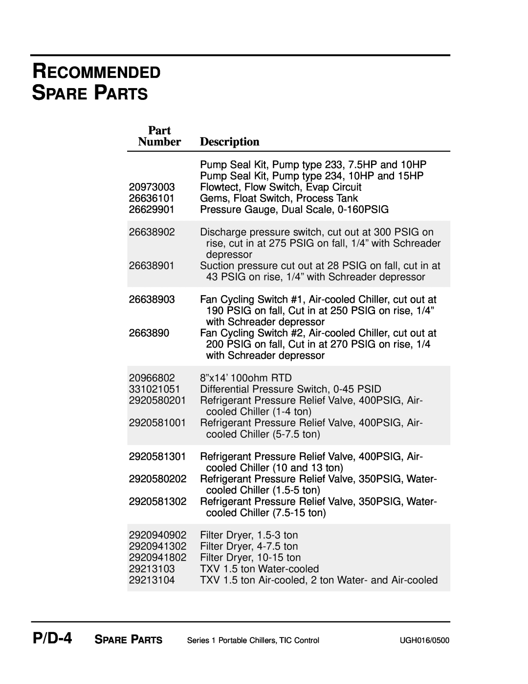
Part Number Description
RECOMMENDED SPARE PARTS
P/D-2
Motor Starter Protector 20.0-25.0A
RECOMMENDED SPARE PARTS
Part Number Description
Part Number Description
20973003 Flowtect, Flow Switch, Evap Circuit
RECOMMENDED SPARE PARTS
29213105 TXV 2 ton Water- and Air-cooled
RECOMMENDED SPARE PARTS
Part Number Description
Condenser Fan Motor, 1/2HP, 575V, 60Hz, for A1-7.5
RECOMMENDED SPARE PARTS
Part Number Description