Product Reference Guide
Datalogic Scanning, Inc
Table of Contents
Data Editing
Iii
Imaging Commands
Appendix a Symbologies
PowerScan 7000 2D
Getting Started
About This Manual
Manual Conventions
Resetting the Standard Product Defaults
Standard Product Default Settings
Table assume the feature is enabled. See
LED and Beeper Indications
Gramming information Condition
Condition Yellow LED Beeper
Connecting the imager with an RS-232 Serial Port
Plug and Play
This interface applies to USB compatible mod- els only
Connecting the imager with USB
RS-232 Interface
IBM SurePos
Face applies to your unit
Symbology Suffix
USB PC Keyboard or USB Macintosh Key- board
CTS/RTS Emulation
No extra configuration e.g., baud rate is neces- sary
USB COM Port Emulation
Connecting the imager in Universal Key- board Wedge mode
ACK/NAK Mode
Cable Connector
Terminal ID
Faces
Supported Terminals
Models
Keyboard Country
@ $ # = / ‘ \ ~
Slovakia Spain Sweden Switzerland German
Keyboard Style
Turkey F Turkey Q
Regular
Caps Lock
Emulate External Keyboard
Automatic Caps Lock
Autocaps via NumLock
Control + Ascii Mode On Control + Ascii Mode Off
Turbo Mode On Turbo Mode Off
Numeric Keypad Mode On Numeric Keypad Mode Off
Keyboard Modifiers
300 600 1200 2400 4800 9600 19200 38400 57,600 115,200
RS-232 Modifiers
RS-232 Baud Rate
RS-232 Word Length Data Bits, Stop Bits, and Parity
RS-232 Receiver Time-Out
RS-232 Receiver Time-Out
RS-232 Handshaking
Terminal Interfaces
Beeper Good Read
Good Read Indicators
Image VGA
Beeper Volume Good Read
Beeper Pitch Good Read
Low Medium High Off
Low 1400 Hz Medium 2800 Hz High 3100 Hz
Beeper Duration Good Read
LED Good Read
Number of Beeps Good Read
Normal Beep Short Beep
Good Read Delay
User-Specified Good Read Delay
User-Specified Good Read Delay
Trigger Modes
Read Time-Out
Manual Trigger, Low Power
Low Power Time-Out Timer
Low Power Time-Out
Scan Stand Symbol
Scan Stand Mode
Presentation Mode
Presentation LED Timer
Hands Free Time-Out
Presentation Sensitivity
LEDs On LEDs Off
Double Read Timeout
User-Specified Double Read Timeout
User-Specified Double Read Timeout
Hands Free Time-Out
LED Power Level
Off Low 50% High 100%
Illumination Lights
Imager Time-Out
Lights On Lights Off
Imager Time-Out
Aimer Delay
User-Specified Aimer Delay
Delay Duration
Milliseconds
Aimer Mode Off
Interlaced Mode
Concurrent Mode
Aimer Modes
Centering
Off Concurrent Interlaced
Centering
Full Omnidirectional
Decode Search Mode
This search mode is the default setting
Output Sequence Overview
Require Output Sequence
Quick Omnidirectional
Advanced Linear Decoding
These options
Output Sequence Editor
To Add an Output Sequence
Code 93 must be enabled to use this example
Output Sequence Examples
Other Programming Selections
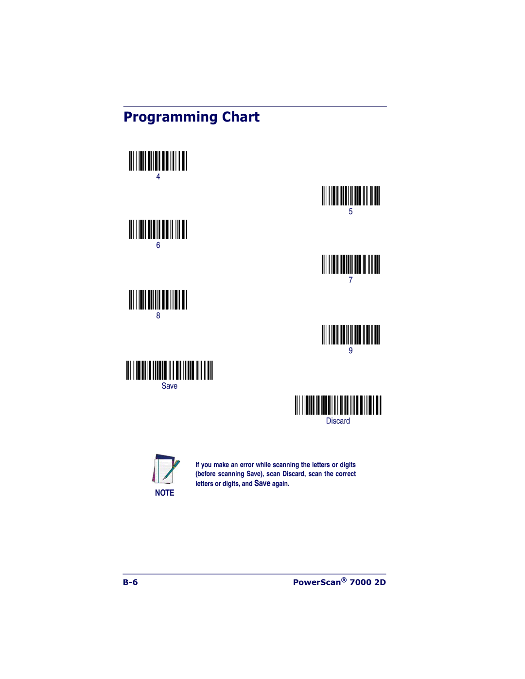
Discard
Breakdown of the command line is shown below
SEQBLK62001141FF6A001242FF69001143FF
Enter Sequence Default Sequence
Required On/Not Required Off
Multiple Symbols
No Read
Video Reverse
Print Weight
Set Print Weight Default
Working Orientation
Upright Rotate Clockwise Upside Down Rotate Counterclockwise
Data Editing
Prefix/Suffix Overview
Points to Keep In Mind
To Add a Prefix or Suffix
Example Add a Suffix to a specific symbology
Add CR Suffix All Symbologies
To Clear One or All Prefixes or Suffixes
To Add a Carriage Return Suffix to all Sym- bologies
Function Code Transmit
Prefix Selections
Suffix Selections
Intercharacter Delay
Intercharacter, Interfunction, and Intermessage Delays
Intercharacter Delay
User Specified Intercharacter Delay
Interfunction Delay
Delay Length Character to Trigger Delay
Interfunction Delay
Intermessage Delay
Intermessage Delay
Data Formatting
Data Format Editor Introduction
Length
To Add a Data Format
Wildcard for all terminal types is
Other Programming Selections
Data Format Editor Commands
Send Commands
Miscellaneous Commands
Move Commands
Search Commands
Data Format Editor
Data Formatter
Data Formatter Off
Data Format On, Format Required
Alternate Data Formats
Alternate Data Format
Symbologies
Linear Symbologies
All Symbologies
All Symbologies On All Symbologies Off
Message Length Description
Codabar Enable
Codabar
Codabar Start/Stop Characters
Codabar Check Character
Codabar Concatenation
Codabar
Code 39 Enable
Code
Codabar Message Length
Code 39 Start/Stop Characters
Code 39 Check Character
Code 39 Message Length
Code 39 Append
Code 32 Pharmaceutical Paraf or Pharmacode
Full Ascii
Full Ascii On Full Ascii Off
Interleaved 2 of 5 Enable
Interleaved 2
Code 39 Code
Check Digit
Interleaved 2 of 5 Message Length
Default All Code 93 Settings
Code 93 Enable
Code 93 Message Length
Code 93 Code
Default All Code 2 of 5 Settings
Code 2 of 5 Enable
Code 2
Code 2 of 5 Message Length
Default All Code Iata 2 of 5 Settings
Iata Code 2 of 5 Enable
Iata Code 2
Iata Code 2 of 5 Message Length
Matrix 2 of 5 Enable
Code 11 Enable
Matrix 2
Matrix 2 of 5 Message Length
Code 11 Message Length
Check Digits Required
One Check Digit Two Check Digits
Isbt 128 Concatenation
Default All Code 128 Settings
Code 128 Enable
Default All Telepen Settings
Code 128 Message Length
Code 128 Code
Code 128 Code
Telepen Message Length
Telepen Output
AIM Telepen Output Original Telepen Output
Default All UPC-A Settings
UPC-A Enable
UPC-A Check Digit Transmit
UPC-A Number System
UPC-A Addenda
Digit Addenda On Digit Addenda Off
UPC-A Addenda Required
Required Not Required
Default All UPC-E Settings
With Extended Coupon Code
UPC-E0 On UPC-E0 Off
UPC-E0 Expand
UPC-E0 Check Digit Transmit
UPC-E0 Addenda Required
UPC-E0 Addenda Separator
UPC-E1 On UPC-E1 Off
UPC-E0 Number System
UPC-E0 Addenda
Default All EAN/JAN Settings
EAN/JAN-13 Enable
EAN/JAN-13 Check Digit Transmit
EAN/JAN-13 Addenda
Isbn Translate
EAN/JAN-13 Addenda Required
EAN/JAN-13 Addenda Separator
Default All EAN/JAN-8 Settings
EAN/JAN-8 Enable
EAN/JAN-8 Check Digit Transmit
EAN/JAN-8 Addenda
EAN/JAN-8 Addenda Required
EAN/JAN-8 Addenda Separator
MSI Check Character
Default All MSI Settings
MSI Enable
Default All Plessey Code Settings
Plessey Code Enable
Plessey Code
MSI Message Length
RSS-14 Enable
RSS Limited Enable
RSS-14
RSS Limited
Default All RSS Expanded Settings
RSS Expanded Enable
RSS Expanded
RSS Expanded Message Length
Default All PosiCode Settings
PosiCode a and B Enable
PosiCode
B On No Limited B and Limited a On Limited B Off
Stacked Symbologies
Codablock F Enable
Trioptic Code
Codablock F
Default All Code 16K Settings
Code 16K Enable
Code 16K
Code 16K Message Length
Code 49 Message Length
Default All Code 49 Settings
Code 49 Enable
Symbologies
Eanucc Composite Codes
UPC/EAN Version
UPC/EAN Version On UPC/EAN Version Off
Eanucc Composite Code Message Length
Eanucc Emulation
Tcif Linked Code 39 TLC39
RSS Emulation Eanucc Emulation Off
Postal Codes
Postnet
Postnet Check Digit Transmit
Transmit Check Digit Don’t Transmit Check Digit
Planet Code
Planet Code Check Digit Transmit
Kix Netherlands Post
British Post
Canadian Post
Default All China Post Settings
Australian Post
Japanese Post
China Post
China Post Enable
Default All Korea Post Settings
Korea Post
China Post Message Length
Default All QR Code Settings
QR Code
Korea Post
Korea Post Message Length
Default All Data Matrix Settings
Data Matrix
QR Code
QR Code Message Length
Data Matrix Enable
Default All MaxiCode Settings
MaxiCode
Data Matrix Message Length
MaxiCode Enable
Default All Aztec Code Settings
Aztec Code
MaxiCode Message Length
Aztec Code Enable
Enable Runes Disable Runes
Aztec Code Message Length
Aztec Runes
Symbologies
Imaging Commands
Image Snap Imgsnp
Imgsnp Modifiers
Image Snap Imgsnp
Image Ship Imgshp
Imgshp Modifiers
Image Ship Imgshp
Imaging Commands
Default = 0, or full image
3S ship every 3rd pixel, both horizontally and vertically
IMGSNP1P0L168W90%32D
IMGBOX40S0X70Y190W100H1R0F
Intelligent Signature Capture
Negative Positive 0123456789
Imgbox Modifiers
Intelligent Signature Capture Imgbox
Imaging Commands
Currency Serial Number Money
Semi Font
OCR Fonts
Default All OCR Settings
OCR symbols can misread when scanned side
Currency Font
OCR-A On
OCR-B On
Currency On
Micr E13 B Font
Semi Font
Micr E 13 B On
Semi Font On
OCR Templates
Creating an OCR Template
Template Characters
To Add an OCR Template
Template Characters
Us, Amount, and Dash
Character Match Sequences
Adding Spaces
Dddddddd
Ddd414243ddd hex codes for letters
551 ABC
Ddddddddtddddlldd
OCR User-Defined Variables
Reading Multi-Row OCR
414243
Ddddddggg
OCR Check Character
OCRTMPdddddddd
OCRTMPllllllll
OCRTMPddddddddrllllllll
OCR Modulo 10 Check Character
OCR Modulo 36 Check Character
Dddddddc
OCR Modulo 10 Check Character
3031323334353637383958
OCR User-Defined Check Character
Programming a User-Defined Check Char- acter
Weighted Modulo Check Character
Weighting Options
Weighted Modulo 10 Check Character
0128454
Ddddddc
OCR Isbn Application Example
OCR Template Codes
Exit Selections
Save OCR Template Discard OCR Template
OCR Programming
Show Data Format
To Add a Test Code I.D. Prefix to All Symbologies
Show Software Revision
Test Menu
2D PQA Print Quality Assessment
Power Image Configurator
Power Image Configurator Operations
Power Image Configurator For RS-232 For USB
Temporary Configuration Using Configura- tor
Installing Power Image Configurator from the Web
Power Image Configurator
Utilities
Serial Programming Commands
Conventions
Menu Command Syntax
Query Commands
Concatenation of Multiple Commands
Tag Field Usage
SubTag Field Usage
Responses
Examples of Query Commands
Trigger Commands
Indicates default
Menu Commands
Setting Serial Selection
Setting
Italy
Country Netherlands Dutch
Slovakia
Keyboard Turbo Mode Off
Modifiers Turbo Mode On
Keyboard Style Automatic Caps Lock
Auto Caps via Num Lock
Beeper Volume Low
Word Length
Data Bits, Stop
Bits, and Parity
Reread Delay Medium 750 ms
Reread Delay
No Delay
Medium Delay 1000 ms
LED Power Level Low 50%
Aimer Delay Milliseconds
Off no delay
Aimer Delay Off
Print Weight Set Print Weight
Add CR Suffix to All Symbologies
Function Code Enable
Transmit Disable
Symbologies
Default All Code
Settings Code Off
Default All Interleaved Interleaved 2
5 Settings Interleaved 2 Off
Default All Code 2
Settings Code 2 Off
Settings Iata Code 2 Off
Iata Code 2
Settings Telepen Off
Matrix 2 Off
Tion
Telepen Output AIM Telepen Output
Default All
UPC-A Settings
Coupon Code Default All UPC-E
UPC-A Check Off
Default All EAN
JAN Settings
JAN 8 Settings
UPC-E0 Check Off
Default All RSS-14
RSS-14 Settings Off
Addenda Digit Addenda Off
Transmit Acter Validate Type 10
Default All RSS-14 RSS Limited
Limited Settings RSS Limited Off
Default All RSS-14 RSS Expanded
Expanded Settings RSS Expanded Off
Code Off
Minimum 1-366 *1
Msg. Length Maximum 1-366 *366
Eanucc Com
Postnet Check Transmit
Digit Don’t Transmit
Planet Code
Planet Code Transmit
MaxiCode Default All MaxiCode Set
Aztec Runes Enable Runes
QR Code Msg Minimum 1-3500 *1
Length Maximum 1-3500 *3500
Imaging Default Commands
Infinity Filter Off
Infinity Filter On
Compensation Off
Compensation On
OCR Selections
456789
456789ABCDE
Acter OCR User-Defined Check
Char
10-28 PowerScan 7000 2D
Imager Product Specifications
Parameter Specification
Power Supply
Temperature Ranges Operating
Noise Rejection Mechanical Shock
22θF to 122θ F -30θC to +50θ C
Pin RJ41 Modular Plug
Standard Cable Pinouts Primary Interface Cables
Serial Output
Standard Cable Pinouts
Pin Modular Plug
Symbology Chart
AIM
Symbology
Code ID
QR/Micro QR Code
Stop
Tcif Linked Code 39 TLC39
Trioptic Code
Ascii Conversion Chart Code
Ascii Conversion Chart Code
PowerScan 7000 2D
Standard Description
Code Page Mapping of Printed Bar Codes
Code Page option is available for Code Code 93, and Code
PowerScan 7000 2D
Sample Symbols
Sample Symbols
Data Matrix QR Code
Sample Symbols
Aztec
OCR Programming Chart
Save Discard
Programming Chart
Programming Chart
Programming Chart
PowerScan 7000 2D
Page
Datalogic Scanning, Inc