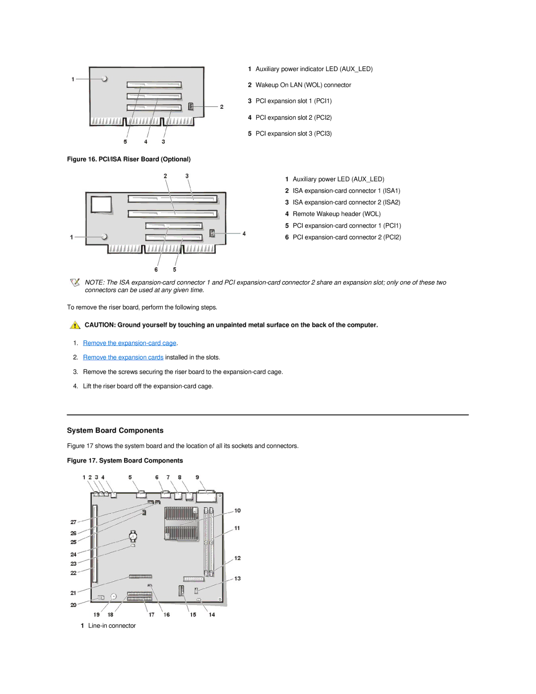
1Auxiliary power indicator LED (AUX_LED)
2Wakeup On LAN (WOL) connector
3PCI expansion slot 1 (PCI1)
4PCI expansion slot 2 (PCI2)
5PCI expansion slot 3 (PCI3)
Figure 16. PCI/ISA Riser Board (Optional)
1 Auxiliary power LED (AUX_LED)
2 ISA
3 ISA
4 Remote Wakeup header (WOL)
5 PCI
6 PCI
NOTE: The ISA
To remove the riser board, perform the following steps.
CAUTION: Ground yourself by touching an unpainted metal surface on the back of the computer.
1.Remove the
2.Remove the expansion cards installed in the slots.
3.Remove the screws securing the riser board to the
4.Lift the riser board off the
System Board Components
Figure 17 shows the system board and the location of all its sockets and connectors.
Figure 17. System Board Components
1