CAUTION: To avoid the possibility of electric shock, turn off the computer and any peripherals, disconnect them from electrical outlets, and then wait at least 5 seconds before you remove the computer cover. Also, before you install a drive, see the other precautions in "Precautionary Measures."
NOTICE: To avoid possibly damaging the drive by ESD, ground yourself by touching an unpainted metal surface on the back of the computer.
NOTICE: When you unpack the drive, do not set it on a hard surface, which may damage the drive. Instead, set the drive on a surface, such as a foam pad, that will sufficiently cushion it.
1.Prepare the drive for installation.
Check the documentation for the drive to verify that it is configured for your computer system.
2.If not already done, remove the computer cover.
3.If not already done, remove the drive bracket from the chassis.
4.Slide the drive into the chosen bay of the bracket, orienting the drive so that the connectors on the back of the drive will face the back of the chassis when you reinstall the bracket (see Figure 18).
5.Align the four screw holes of the drive and bracket. Insert and tighten the screws from the
•If you are installing a drive in the
•If you are installing a drive in the
6.Reinstall the
a.Insert the bracket's hinge tabs into the chassis hinge slots so that the tabs hook over the hinge slots.
b.Rotate the bracket toward the chassis, and fit the bracket's sliding tab on the chassis slide rail.
c.Slide the bracket into place, and reinstall the screw you removed in step 4 of the previous procedure.
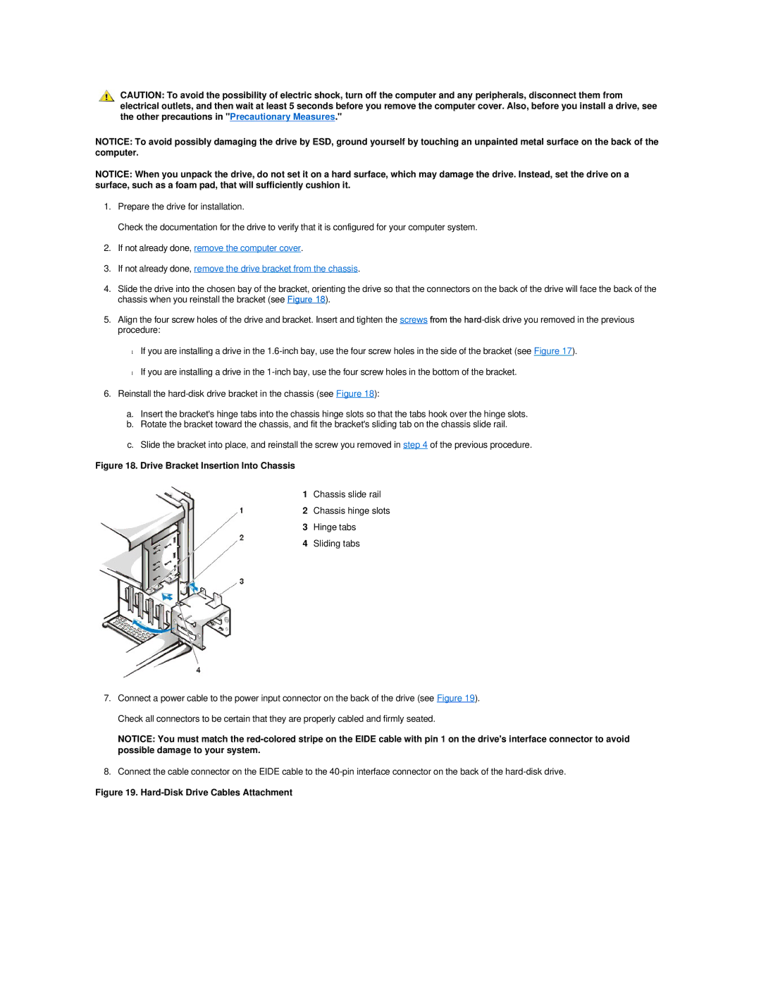
Figure 18. Drive Bracket Insertion Into Chassis
1Chassis slide rail
2Chassis hinge slots
3Hinge tabs
4Sliding tabs
7.Connect a power cable to the power input connector on the back of the drive (see Figure 19). Check all connectors to be certain that they are properly cabled and firmly seated.
NOTICE: You must match the
8.Connect the cable connector on the EIDE cable to the