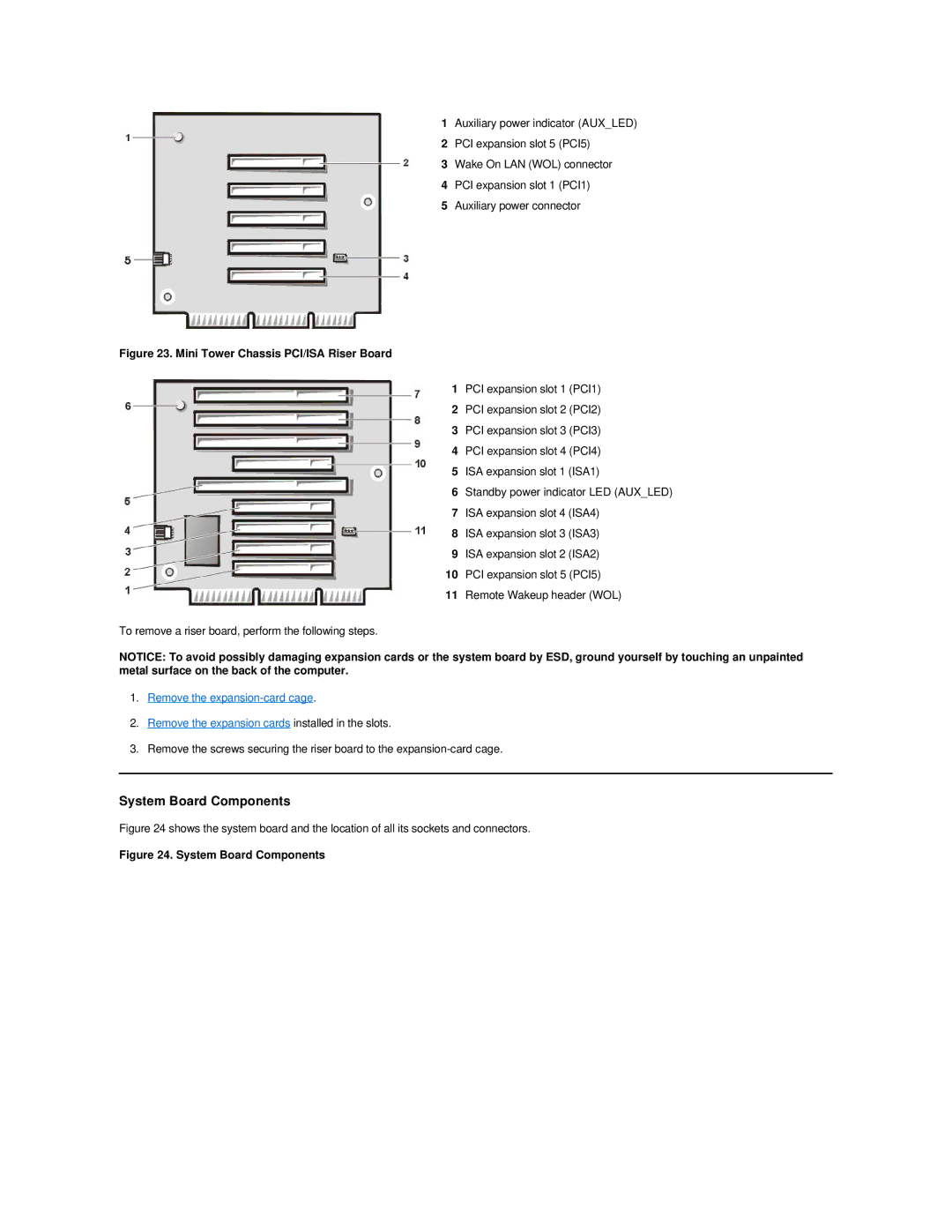
1Auxiliary power indicator (AUX_LED)
2PCI expansion slot 5 (PCI5)
3Wake On LAN (WOL) connector
4PCI expansion slot 1 (PCI1)
5Auxiliary power connector
Figure 23. Mini Tower Chassis PCI/ISA Riser Board
1PCI expansion slot 1 (PCI1)
2PCI expansion slot 2 (PCI2)
3PCI expansion slot 3 (PCI3)
4PCI expansion slot 4 (PCI4)
5ISA expansion slot 1 (ISA1)
6Standby power indicator LED (AUX_LED)
7ISA expansion slot 4 (ISA4)
8ISA expansion slot 3 (ISA3)
9ISA expansion slot 2 (ISA2)
10PCI expansion slot 5 (PCI5)
11Remote Wakeup header (WOL)
To remove a riser board, perform the following steps.
NOTICE: To avoid possibly damaging expansion cards or the system board by ESD, ground yourself by touching an unpainted metal surface on the back of the computer.
1.Remove the
2.Remove the expansion cards installed in the slots.
3.Remove the screws securing the riser board to the