| MONITOR | Video connector |
|
|
|
|
|
| MOUSE | Mouse connector |
|
|
|
|
|
|
|
|
|
| PANEL | Control panel connector |
|
|
|
|
|
|
|
|
|
| PARALLEL | Parallel port connector; sometimes referred to as LPT1 |
|
|
|
|
|
|
|
|
|
| PCIn* | PCI |
|
|
|
|
|
|
|
|
|
| POWER_1 | Main power input connector |
|
|
|
|
|
|
|
|
|
| POWER_2 |
| |
|
|
|
|
|
|
|
|
| RISER | Riser board connector |
|
|
|
|
|
|
|
|
|
| SERIALn | Serial port connector |
|
|
|
|
|
|
|
|
|
| SLOT1_PRI | Primary microprocessor connector |
|
|
|
|
|
|
|
|
|
| USB | USB connectors |
|
|
|
|
|
|
|
|
|
|
|
|
|
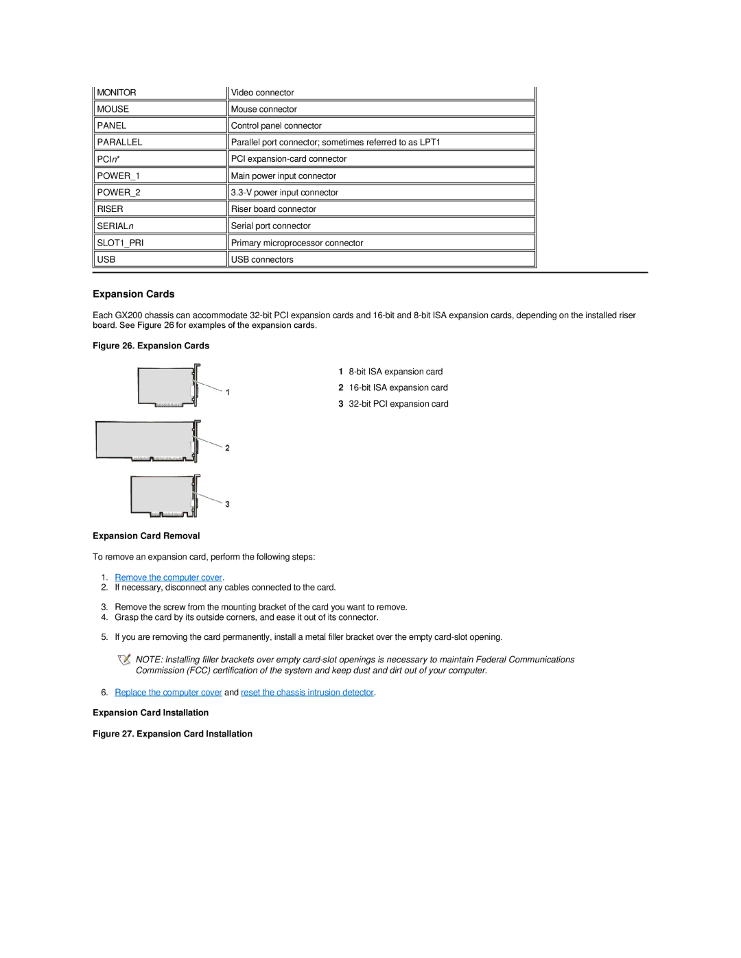
Expansion Cards
Each GX200 chassis can accommodate
Figure 26. Expansion Cards
1
2
3
Expansion Card Removal
To remove an expansion card, perform the following steps:
1.Remove the computer cover.
2.If necessary, disconnect any cables connected to the card.
3.Remove the screw from the mounting bracket of the card you want to remove.
4.Grasp the card by its outside corners, and ease it out of its connector.
5.If you are removing the card permanently, install a metal filler bracket over the empty
![]() NOTE: Installing filler brackets over empty
NOTE: Installing filler brackets over empty
6.Replace the computer cover and reset the chassis intrusion detector.