Dell Inspiron XPS
Abbreviations and Acronyms
Contents
Optimizing Performance
Using the Keyboard and Touch Pad
Resolving Software and Hardware Incompatibilities Contents
Adding and Replacing Parts
Appendix
183
Contents
Safety General
Safety Battery
Safety Power
Safety Air Travel
Safety EMC Instructions
When Using Your Computer
Safety When Working Inside Your Computer
Safety Ergonomic Computing Habits
Safety Protecting Against Electrostatic Discharge
Safety Battery Disposal
Safety Instructions
Finding Information
Dell Solution Center
Setup Diagram
Dell Support Website support.dell.com
Finding Information
Front View
Tour of Your Computer
Device Status Lights
Tour of Your Computer
Keyboard Status Lights
Left Side View
Right Side View
Back View
Video Connector
Modem Connector RJ-11
W . d e l l . c o m s u p p o r t . d e l l . c o m
Bottom View
Tour of Your Computer
Transferring Information to a New Computer
Using Your Computer
Settings and Functions
Configuring Graphics Cards
Click Finished and restart the new computer
Click User and system guides
Connecting Your Computer to a TV or Audio Device
Video and Standard Audio
Video and S/PDIF Digital Audio
Pdif digital audio cable
Composite Video and Standard Audio
Composite Video and S/PDIF Digital Audio
Using Your Computer
Enabling S/PDIF Digital Audio
Setting Up the Dolby Headphone
Enabling the Display Settings for a TV
Connecting Monitors
Connect the VGA or DVI monitor as described on
How to Copy a CD or DVD
Using CDs and DVDs
Copying CDs and DVDs
Helpful Tips
Using Blank CD-Rs, CD-RWs, DVD+Rs, and DVD+RWs
Hyper-Threading
DDR Memory and Processor Front-Side Bus
Optimizing Performance
Battery Performance
Using a Battery
Dell QuickSet Battery Meter
Checking the Battery Charge
Microsoft Windows Power Meter
Charge Gauge
Low-Battery Warning
Charging the Battery
Removing a Battery
Storing a Battery
Installing a Battery
Using a Battery
About the Module Bay
Using the Module Bay
Push the new device into the bay until it clicks
Pull the device out of the module bay
Press the device latch release
Using the Module Bay
Numeric Keypad
Battery
Key Combinations
System Functions
Display Functions
Power Management
Speaker Functions
Microsoft Windows Logo Key Functions
Touch Pad
Customizing the Touch Pad and Track Stick
Changing the Track Stick Cap
Using the Keyboard and Touch Pad
Connecting to a Network Adapter
Setting Up a Home and Office Network
Connecting to a Wireless Local Area Network
Network Setup Wizard
Determining Your Network Type
Connecting to a Wireless Network in Microsoft Windows XP
Click Add Wireless network properties window appears
Setting Up a Home and Office Network
Configuring Security Settings Optional
Setting Up a Home and Office Network
Setting Up a Home and Office Network
Setting Up a Home and Office Network
Setting Up a Home and Office Network
When to Use the Dell Diagnostics
Using the Dell Diagnostics
Option Function Express Test
Device
Error Messages
Message 1 files copied appears
If the display is blank
Video and Display Problems
If only part of the display is readable
If the display is difficult to read
Hard Drive Problems
Scanner Problems
If you have problems with a hard drive
External Keyboard Problems
PC Card Problems
Power Problems
Unexpected Characters
Touch Pad or Mouse Problems
Printer Problems
Modem and Internet Connection Problems
Mail Problems
Restart the Computer Try to log on to the network again
Network Problems
Error messages appear
General Program Problems
Program crashes
Program stops responding
If you cannot play a CD, CD-RW, or DVD
CD or DVD Problems
If you cannot eject the CD, CD-RW, or DVD drive tray
If you have a problem with integrated speakers
Sound and Speaker Problems
If you hear an unfamiliar scraping or grinding sound
If the CD-RW drive stops writing
If you have a problem with external speakers
Mail, Modem, and Internet Problems
What Is a Driver?
Resolving Other Technical Problems
Drivers
Identifying Drivers
Reinstalling Drivers and Utilities
Insert the Drivers and Utilities CD
Click the Drivers tab Click Roll Back Driver
Resolving Software and Hardware Incompatibilities
Creating a Restore Point
Using Microsoft Windows XP System Restore
Select a restore point and click Next
Restoring the Computer to an Earlier Operating State
Undoing the Last System Restore
Reinstalling Microsoft Windows XP
Before You Begin
To reinstall Windows XP, you need the following items
Reinstalling Windows XP
When the Welcome to Microsoft screen appears, click Next
101
Solving Problems
Recommended Tools
Before You Begin
Shutting Down Your Computer
103
Adding and Replacing Parts
105
Memory
Memory module Securing clips 2 per connector
107
108
Mini PCI Card
109
Adding and Replacing Parts
111
Hard Drive
112
Returning a Hard Drive to Dell
113
Subwoofer
Keyboard
Insert the subwoofer into the compartment within the battery
115
116
PC Card With Bluetooth Wireless Technology
Removing the Modem
Modem
117
Keyboard Bracket
Installing the Modem
Connect the modem cable to the modem
Replace the M2 x 3-mm screw
119
Fans
Fan cover Captive screws Audio connectors
121
Hinge Covers
Left hinge cover
123
Display
125
126
127
Display Latch
Remove the two M2 x 4-mm screws and remove the display latch
Video Card
Removing the Processor Thermal-Cooling Assembly
Processor Thermal-Cooling Assembly
129
Palm Rest
Installing the Processor Thermal-Cooling Assembly
131
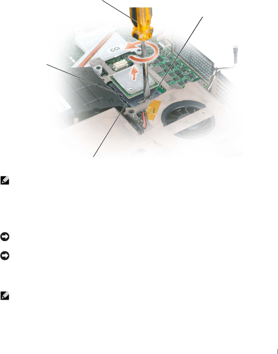
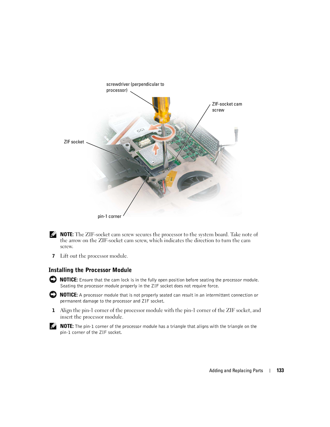
Removing the Processor Module
Processor Module
132
133
Installing the Processor Module
Reserve Battery
Flashing the Bios
134
Removing the System Board
System Board
135
136
Remove the keyboard see Remove the display see
137
Installing the System Board
138
Speakers
139
Display Latch Release
USB Connector
Pin Assignments for I/O Connectors
Video Connector
140
Ieee 1394 Connector
Video TV-Out Connector
141
142
DVI-I Connector
143
Specifications
USB
144
Lvds
145
Wuxga WSXGA+ Wxga
146
147
148
Overview
Using the System Setup Program
149
System Setup Screens
Viewing the System Setup Screens
Commonly Used Options
150
151
Enabling the Infrared Sensor
Dell Technical Support Policy U.S. Only
Definition of Dell-Installed Software and Peripherals
Contacting Dell
Definition of Third-Party Software and Peripherals
153
154
155
156
157
158
159
160
161
162
163
164
165
166
167
168
169
170
Regulatory Notices
What is not covered by this limited warranty?
What is covered by this limited warranty?
Limited Warranties
NOM Information Mexico Only
172
How long does this limited warranty last?
What will Dell do?
What do I do if I need warranty service?
173
May I transfer the limited warranty?
What if I purchased a service contract?
How will you fix my product?
174
175
176
Third-Party Software and Peripherals Products
Dell Software and Peripherals Canada Only
177
Dell-Branded Peripheral Products
Guarantee
Return Policy
Exclusions
179
Limitation and Statutory Rights
180
Intel’s Three Year Limited Warranty
What are Errata?
181
Appendix
Index
Microsoft Windows
Specifications, system Spyware
Track stick, 62 description, 23 system view