| the remote access controller (RAC) card. See the BMC User's Guide for more information on setup and use of BMC. |
<Ctrl><C> | This keystroke enters the SAS Configuration Utility. See your SAS controller User's Guide for more information. |
|
|
<Ctrl><R> | If you have the optional |
| documentation for your SAS controller card. |
<Ctrl><S> | If you have PXE support enabled through the System Setup Program (see Integrated Devices Screen), this keystroke allows you to configure |
| NIC settings for PXE boot. For more information, see the documentation for your integrated NIC. |
|
|
|
|
Front-Panel Features and Indicators
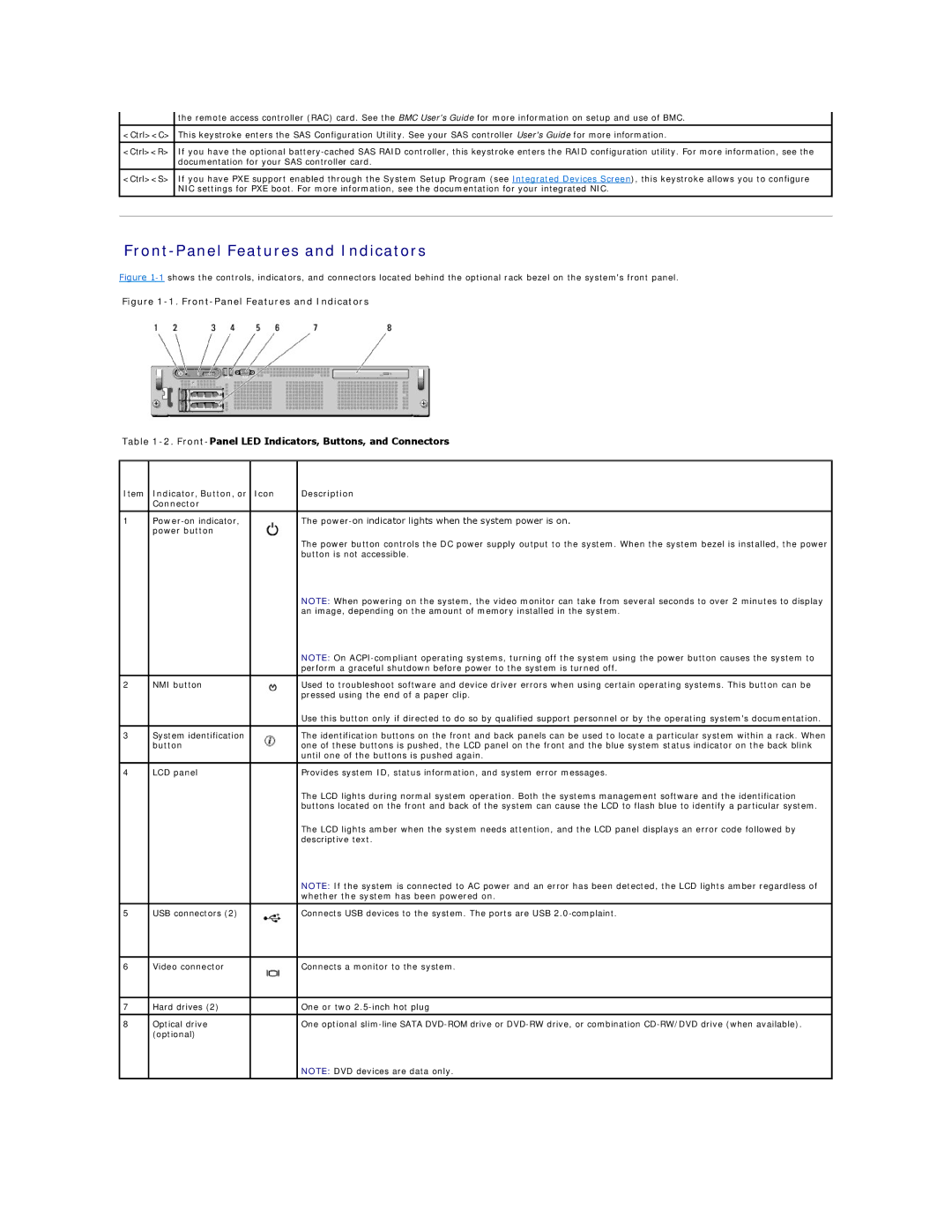
Figure 1-1 shows the controls, indicators, and connectors located behind the optional rack bezel on the system's front panel.
Figure 1-1. Front-Panel Features and Indicators
Table 1-2. Front-Panel LED Indicators, Buttons, and Connectors
Item | Indicator, Button, or | Icon | Description |
| Connector |
|
|
|
|
|
|
1 |
| The | |
| power button |
|
|
|
|
| The power button controls the DC power supply output to the system. When the system bezel is installed, the power |
|
|
| button is not accessible. |
|
|
| NOTE: When powering on the system, the video monitor can take from several seconds to over 2 minutes to display |
|
|
| an image, depending on the amount of memory installed in the system. |
|
|
| NOTE: On |
|
|
| perform a graceful shutdown before power to the system is turned off. |
2 | NMI button |
| Used to troubleshoot software and device driver errors when using certain operating systems. This button can be |
|
|
| pressed using the end of a paper clip. |
|
|
| Use this button only if directed to do so by qualified support personnel or by the operating system's documentation. |
|
|
|
|
3 | System identification |
| The identification buttons on the front and back panels can be used to locate a particular system within a rack. When |
| button |
| one of these buttons is pushed, the LCD panel on the front and the blue system status indicator on the back blink |
|
|
| until one of the buttons is pushed again. |
4 | LCD panel |
| Provides system ID, status information, and system error messages. |
|
|
| The LCD lights during normal system operation. Both the systems management software and the identification |
|
|
| buttons located on the front and back of the system can cause the LCD to flash blue to identify a particular system. |
|
|
| The LCD lights amber when the system needs attention, and the LCD panel displays an error code followed by |
|
|
| descriptive text. |
|
|
| NOTE: If the system is connected to AC power and an error has been detected, the LCD lights amber regardless of |
|
|
| whether the system has been powered on. |
|
|
|
|
5 | USB connectors (2) |
| Connects USB devices to the system. The ports are USB |
|
|
|
|
6 | Video connector |
| Connects a monitor to the system. |
|
|
|
|
7 | Hard drives (2) |
| One or two |
|
|
|
|
8 | Optical drive |
| One optional |
| (optional) |
|
|
|
|
| NOTE: DVD devices are data only. |
|
|
|
|