![]() 1
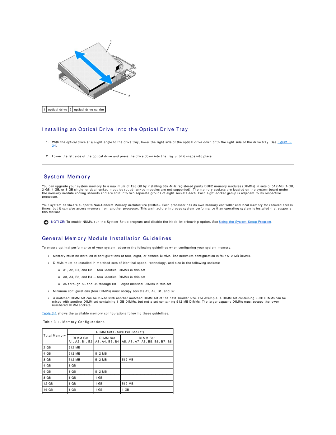
1 ![]() optical drive
optical drive ![]() 2
2 ![]() optical drive carrier
optical drive carrier ![]()
Installing an Optical Drive Into the Optical Drive Tray
1.With the optical drive at a slight angle to the drive tray, lower the right side of the optical drive down onto the right side of the drive tray. See Figure 3- 24.
2.Lower the left side of the optical drive and press the drive down into the tray until it snaps into place.
System Memory
You can upgrade your system memory to a maximum of 128 GB by installing
Your system hardware supports
NOTICE: To enable NUMA, run the System Setup program and disable the Node Interleaving option. See Using the System Setup Program.
General Memory Module Installation Guidelines
To ensure optimal performance of your system, observe the following guidelines when configuring your system memory.
•Memory must be installed in configurations of four, eight, or sixteen DIMMs. The minimum configuration is four
•DIMMs must be installed in matched sets of identical speed, technology, and size in the following sockets:
¡A1, A2, B1, and B2 — four identical DIMMs in this set
¡A3, A4, B3, and B4 — four identical DIMMs in this set
¡A5 through A8 and B5 through B8 — eight identical DIMMs in this set
•Minimum configurations (four DIMMs) must occupy sockets A1, A2, B1, and B2.
•A matched DIMM set can be mixed with another matched DIMM set of the next smaller size. For example, a DIMM set containing
Table
Table 3-1. Memory Configurations
Total Memory |
| DIMM Sets (Size Per Socket) | ||
|
|
| ||
DIMM Set | DIMM Set | DIMM Set | ||
| ||||
| A1, A2, B1, B2 | A3, A4, B3, B4 | A5, A6, A7, A8, B5, B6, B7, B8 | |
|
|
|
| |
2 GB | 512 MB |
|
| |
4 GB | 512 MB | 512 MB |
| |
|
|
|
| |
8 GB | 512 MB | 512 MB | 512 MB | |
|
|
|
| |
4 GB | 1 GB |
|
| |
|
|
|
| |
6 GB | 1 GB | 512 MB |
| |
|
|
|
| |
8 GB | 1 GB | 1 GB |
| |
|
|
|
| |
12 GB | 1 GB | 1 GB | 512 MB | |
|
|
|
| |
16 GB | 1 GB | 1 GB | 1 GB | |
|
|
|
| |
|
|
|
| |