7.Disconnect the power cable from the backplane connector.
8.Disconnect the optical drive power cable from the backplane connector.
9.Remove the sideplane board. See Removing the Sideplane Board.
10.Remove the SAS/SATA backplane board:
a.Pull the backplane board release pin. See Figure
b.While pulling the release pin, tilt the backplane board toward the back of the system.
c.Lift the backplane board from its securing tabs and remove the backplane board from the chassis.
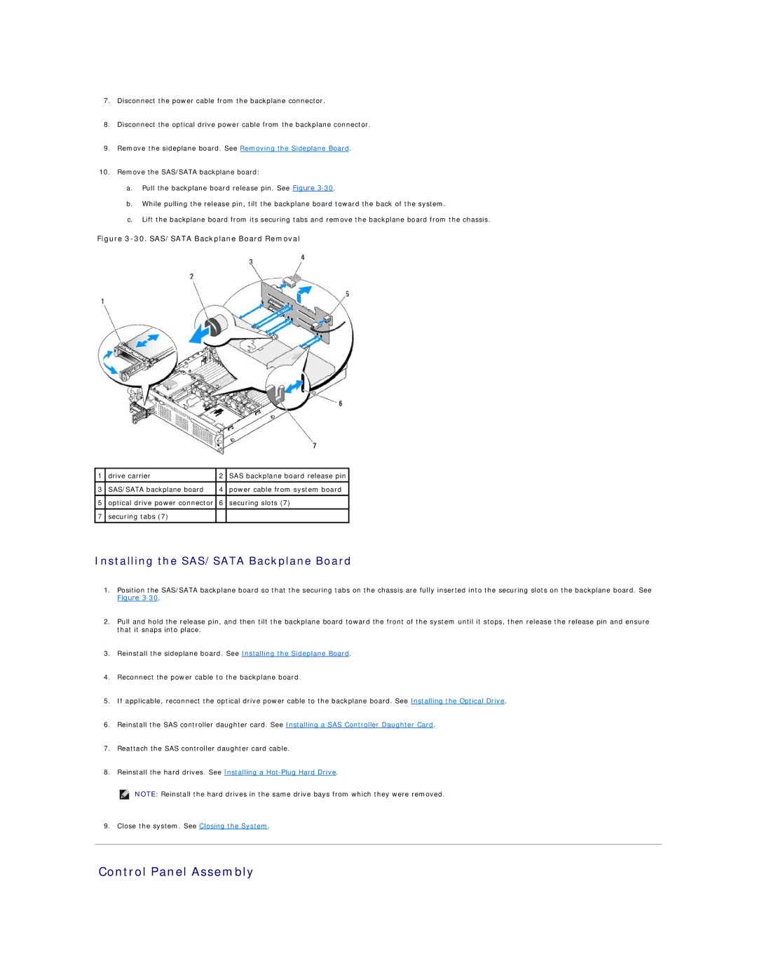
Figure 3-30. SAS/SATA Backplane Board Removal
1 | drive carrier | 2 | SAS backplane board release pin |
|
|
|
|
3 | SAS/SATA backplane board | 4 | power cable from system board |
|
|
|
|
5 | optical drive power connector | 6 | securing slots (7) |
|
|
|
|
7 | securing tabs (7) |
|
|
Installing the SAS/SATA Backplane Board
1.Position the SAS/SATA backplane board so that the securing tabs on the chassis are fully inserted into the securing slots on the backplane board. See
Figure
2.Pull and hold the release pin, and then tilt the backplane board toward the front of the system until it stops, then release the release pin and ensure that it snaps into place.
3.Reinstall the sideplane board. See Installing the Sideplane Board.
4.Reconnect the power cable to the backplane board.
5.If applicable, reconnect the optical drive power cable to the backplane board. See Installing the Optical Drive.
6.Reinstall the SAS controller daughter card. See Installing a SAS Controller Daughter Card.
7.Reattach the SAS controller daughter card cable.
8.Reinstall the hard drives. See Installing a
NOTE: Reinstall the hard drives in the same drive bays from which they were removed.
9. Close the system. See Closing the System.