System Board Connectors
See Figure
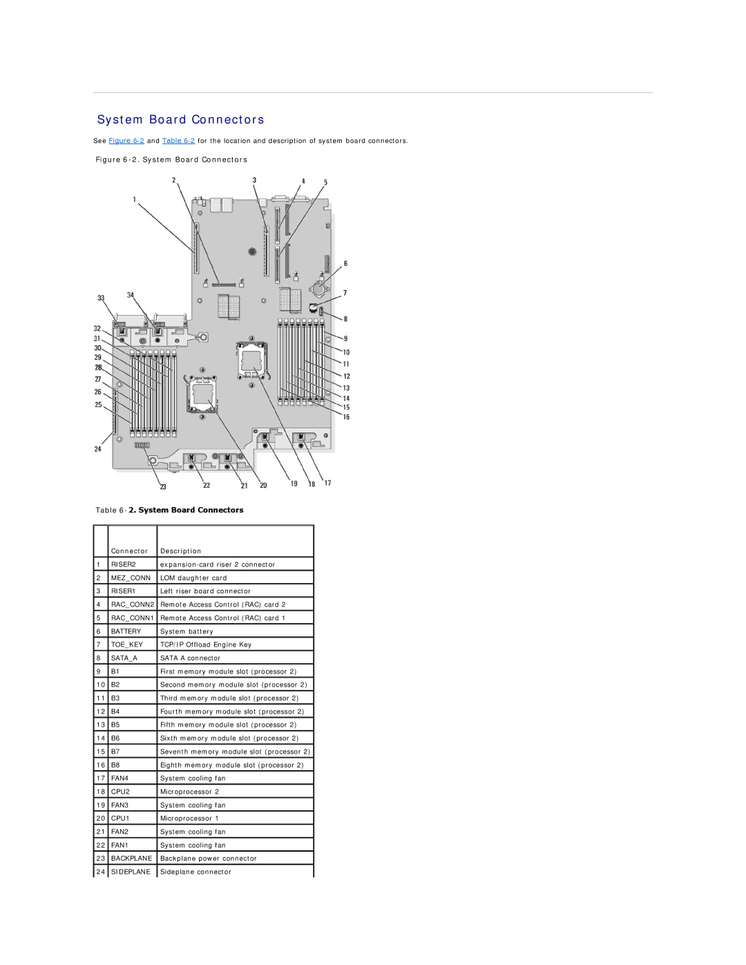
Figure 6-2. System Board Connectors
Table
| Connector | Description |
|
|
|
1 | RISER2 | |
|
|
|
2 | MEZ_CONN | LOM daughter card |
|
|
|
3 | RISER1 | Left riser board connector |
|
|
|
4 | RAC_CONN2 | Remote Access Control (RAC) card 2 |
|
|
|
5 | RAC_CONN1 | Remote Access Control (RAC) card 1 |
|
|
|
6 | BATTERY | System battery |
|
|
|
7 | TOE_KEY | TCP/IP Offload Engine Key |
|
|
|
8 | SATA_A | SATA A connector |
|
|
|
9 | B1 | First memory module slot (processor 2) |
|
|
|
10 | B2 | Second memory module slot (processor 2) |
|
|
|
11 | B3 | Third memory module slot (processor 2) |
|
|
|
12 | B4 | Fourth memory module slot (processor 2) |
|
|
|
13 | B5 | Fifth memory module slot (processor 2) |
|
|
|
14 | B6 | Sixth memory module slot (processor 2) |
|
|
|
15 | B7 | Seventh memory module slot (processor 2) |
|
|
|
16 | B8 | Eighth memory module slot (processor 2) |
|
|
|
17 | FAN4 | System cooling fan |
|
|
|
18 | CPU2 | Microprocessor 2 |
|
|
|
19 | FAN3 | System cooling fan |
|
|
|
20 | CPU1 | Microprocessor 1 |
|
|
|
21 | FAN2 | System cooling fan |
|
|
|
22 | FAN1 | System cooling fan |
|
|
|
23 | BACKPLANE | Backplane power connector |
|
|
|
24 | SIDEPLANE | Sideplane connector |
|
|
|