7 | system identification button | 8 | system status indicator |
9 | system status indicator connector | 10 | LOM4 connector (Gb/10Gb)1 |
|
|
|
|
11 | LOM3 connector (Gb/10Gb)a | 12 | LOM2 connector (Gb) |
|
|
|
|
13 | LOM1 connector (Gb) | 14 | |
|
|
|
|
15 | video connector | 16 | serial connector |
|
|
|
|
17 | remote access controller (RAC) connector (optional) |
|
|
|
|
|
|
Connecting External Devices
When connecting external devices to your system, follow these guidelines:
•Most devices must be connected to a specific connector and device drivers must be installed before the device operates properly. (Device drivers are normally included with your operating system software or with the device itself.) See the documentation that accompanied the device for specific installation and configuration instructions.
•Always attach external devices while your system and the device are turned off. Next, turn on any external devices before turning on the system (unless the documentation for the device specifies otherwise).
For information about individual connectors, see Jumpers and Connectors. For information about enabling, disabling, and configuring I/O ports and connectors, see Using the System Setup Program.
Power Indicator Codes
The power button on the front panel controls the power to the system from the system's power supplies. The power indicator lights green when the system is on.
The indicators on the redundant power supplies show whether power is present or whether a power fault has occurred (see Figure
Table 1-4. Redundant Power Supply Indicators
Indicator | Function |
|
|
Power supply status | Green indicates that the power supply is operational and providing DC power to the system. |
|
|
Power supply fault | Amber indicates a problem with the power supply. |
|
|
AC line status | Green indicates that a valid AC source is connected to the power supply and is operational. |
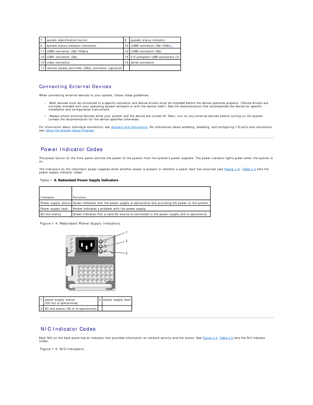
Figure 1-4. Redundant Power Supply Indicators
1 | power supply status | 2 | power supply fault |
|
| (DC out is operational) |
|
|
|
|
|
|
|
|
3 | AC line status (AC in is operational) |
|
|
|
|
|
|
|
|
|
|
|
|
|
NIC Indicator Codes
Each NIC on the back panel has an indicator that provides information on network activity and link status. See Figure