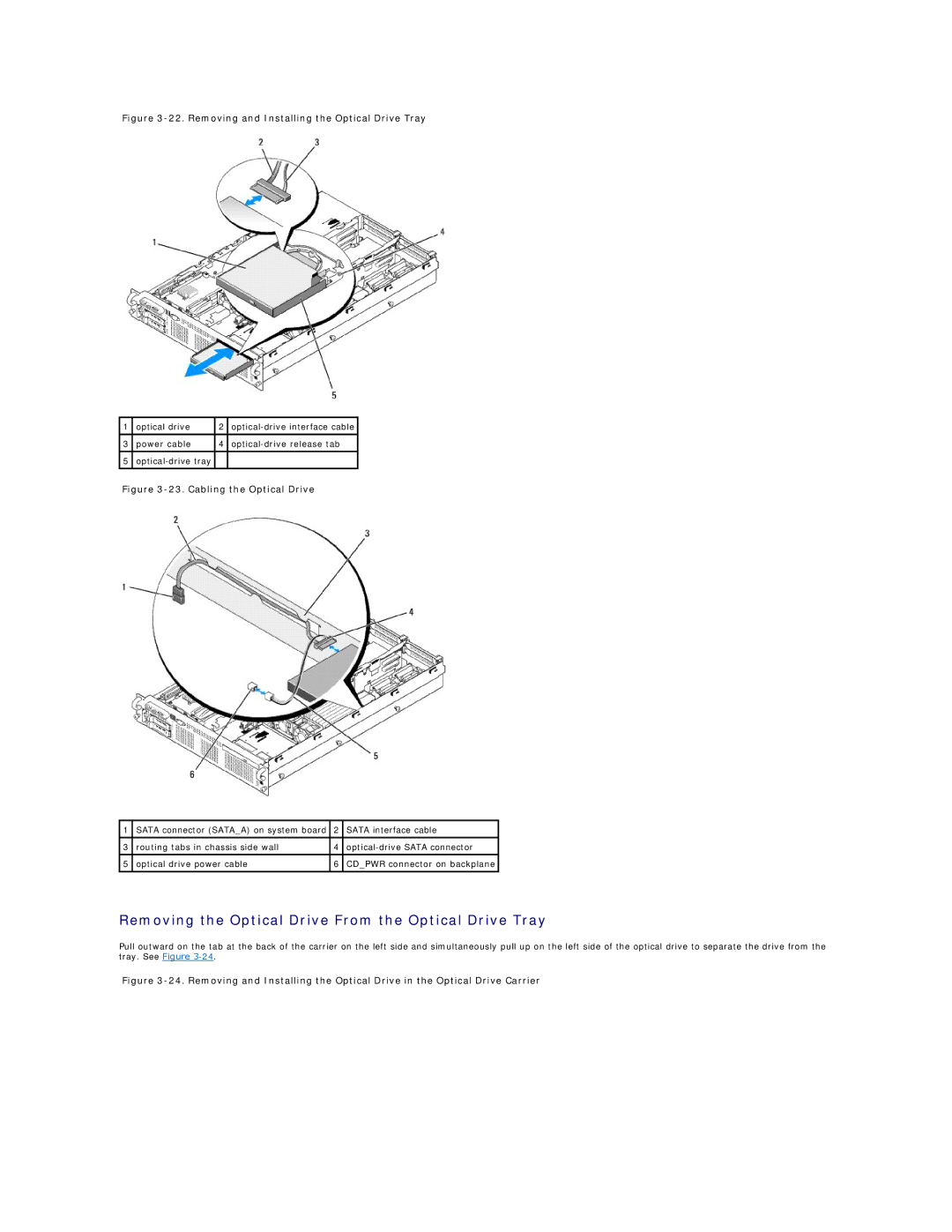
Figure 3-22. Removing and Installing the Optical Drive Tray
1 | optical drive | 2 | |
|
|
|
|
3 | power cable | 4 | |
|
|
|
|
5 |
|
| |
|
|
|
|
Figure 3-23. Cabling the Optical Drive
1 | SATA connector (SATA_A) on system board | 2 | SATA interface cable |
|
|
|
|
3 | routing tabs in chassis side wall | 4 | |
|
|
|
|
5 | optical drive power cable | 6 | CD_PWR connector on backplane |
|
|
|
|
Removing the Optical Drive From the Optical Drive Tray
Pull outward on the tab at the back of the carrier on the left side and simultaneously pull up on the left side of the optical drive to separate the drive from the tray. See Figure