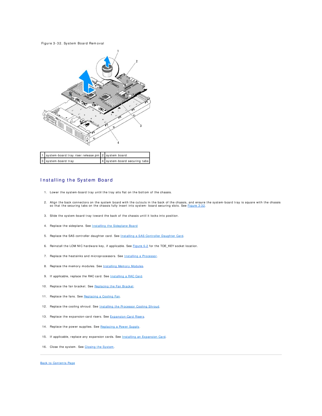
Figure 3-32. System Board Removal
1 | 2 | system board | |
|
|
|
|
3 | 4 | ||
|
|
|
|
Installing the System Board
1.Lower the
2.Align the back connectors on the system board with the cutouts in the back of the chassis, and ensure the
3.Slide the
4.Replace the sideplane. See Installing the Sideplane Board
5.Replace the SAS controller daughter card. See Installing a SAS Controller Daughter Card.
6.Reinstall the LOM NIC hardware key, if applicable. See Figure
7.Replace the heatsinks and microprocessors. See Installing a Processor.
8.Replace the memory modules. See Installing Memory Modules.
9.If applicable, replace the RAC card. See Installing a RAC Card.
10.Replace the fan bracket. See Replacing the Fan Bracket.
11.Replace the fans. See Replacing a Cooling Fan.
12.Replace the cooling shroud. See Installing the Processor Cooling Shroud.
13.Replace the
14.Replace the power supplies. See Replacing a Power Supply.
15.If applicable, replace any expansion cards. See Installing an Expansion Card.
16.Close the system. See Closing the System.