3.Lower the left ("A") memory module shroud over the "A" memory modules and press down lightly to latch the shroud to the processor cooling shroud.
4.Close the system. See Closing the System.
5.Reconnect the system to the electrical outlet and turn on the system and attached peripherals.
Fan Brackets
Removing the Fan Brackets
CAUTION: Many repairs may only be done by a certified service technician. You should only perform troubleshooting and simple repairs as authorized in your product documentation, or as directed by the online or telephone service and support team. Damage due to servicing that is not authorized by Dell is not covered by your warranty. Read and follow the safety instructions that came with the product.
1.Turn off the system, including any attached peripherals, and disconnect the system from the electrical outlet.
2.Open the system. See Opening the System.
3.Remove the fans from the fan bracket. See Removing a System Fan.
4.Remove the expansion cards from riser 2. See Removing an Expansion Card.
5.Remove the
6.Remove all three cooling shrouds. See Cooling Shrouds.
7.For the processor fan bracket only: Remove the SAS controller daughter card. See Removing a SAS Controller Daughter Card.
8.Remove the fan bracket from the system:
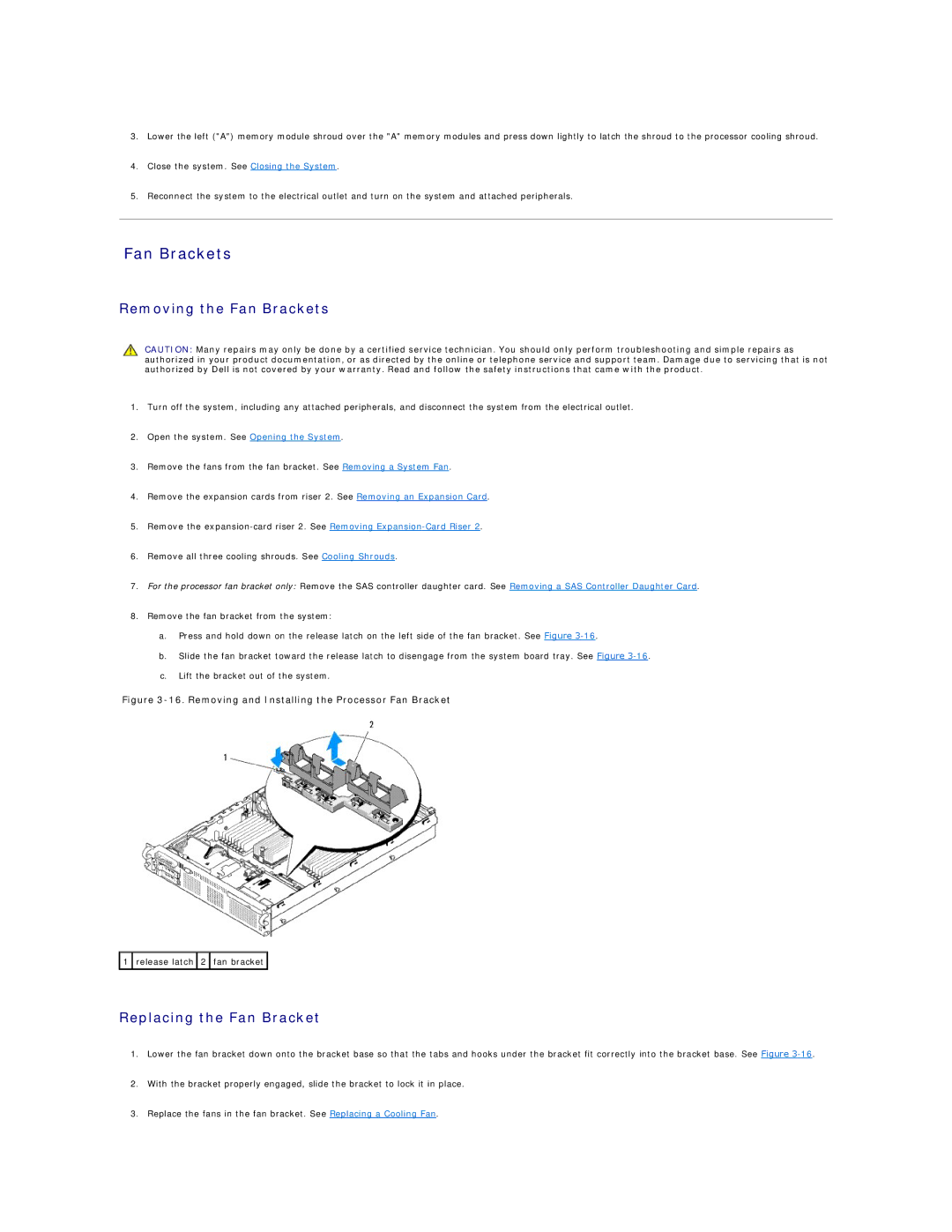
a.Press and hold down on the release latch on the left side of the fan bracket. See Figure
b.Slide the fan bracket toward the release latch to disengage from the system board tray. See Figure
c.Lift the bracket out of the system.
Figure 3-16. Removing and Installing the Processor Fan Bracket
![]() 1
1 ![]() release latch
release latch ![]() 2
2 ![]() fan bracket
fan bracket ![]()
Replacing the Fan Bracket
1.Lower the fan bracket down onto the bracket base so that the tabs and hooks under the bracket fit correctly into the bracket base. See Figure
2.With the bracket properly engaged, slide the bracket to lock it in place.
3.Replace the fans in the fan bracket. See Replacing a Cooling Fan.