Epsilon Ei DeviceNet Drive Reference Manual
Index 1 Velocity is mapped to class 0x68, instance 0x02, attribute 0x09, as shown in the table below.
The following parameters will be used to set up this explicit message.
Interger File N10 | High Byte |
| Low Byte |
N10:0 | TXID=0x01 |
| COMMAND=0x01 |
|
|
|
|
N10:1 | PORT=0x00 |
| SIZE OF DATA FIELD=0x0A |
|
|
|
|
N10:2 | SERVICE=0x10 (SET) |
| MacID=0x04 |
|
|
|
|
N10:3 |
| CLASS=0x68 | |
|
|
| |
N10:4 |
| INSTANCE=0x02 | |
|
|
| |
N10:5 |
| ATTRIBUTE=0x09 | |
|
|
|
|
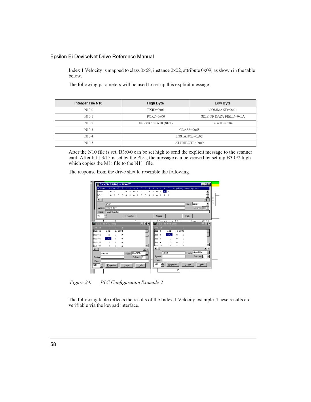
After the N10 file is set, B3:0/0 can be set high to send the explicit message to the scanner card. After bit I:3/15 is set by the PLC, the message can be viewed by setting B3:0/2 high which copies the M1: file to the N11: file.
The response from the drive should resemble the following.
Figure 24: PLC Configuration Example 2
The following table reflects the results of the Index 1 Velocity example. These results are verifiable via the keypad interface.
58
