Stylus C40UX/C40SX/C20UX/C20SX | Revision A |
Step 1
Hopper
LD roller
Step 2
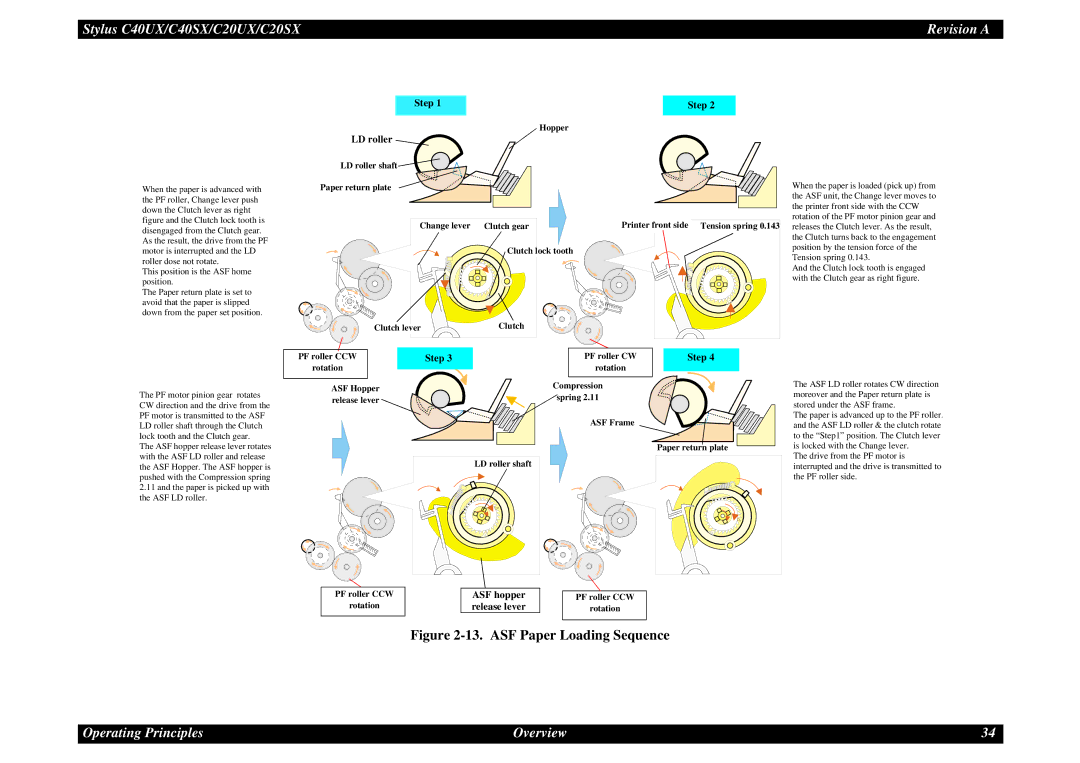
When the paper is advanced with the PF roller, Change lever push down the Clutch lever as right figure and the Clutch lock tooth is disengaged from the Clutch gear. As the result, the drive from the PF motor is interrupted and the LD roller dose not rotate.
This position is the ASF home position.
The Paper return plate is set to avoid that the paper is slipped down from the paper set position.
LD roller shaft![]()
![]()
Paper return plate
Change lever Clutch gear
Clutch lock tooth
Clutch lever | Clutch |
Printer front side
When the paper is loaded (pick up) from the ASF unit, the Change lever moves to the printer front side with the CCW rotation of the PF motor pinion gear and
Tension spring 0.143 releases the Clutch lever. As the result, the Clutch turns back to the engagement position by the tension force of the Tension spring 0.143.
And the Clutch lock tooth is engaged with the Clutch gear as right figure.
The PF motor pinion gear rotates CW direction and the drive from the PF motor is transmitted to the ASF LD roller shaft through the Clutch lock tooth and the Clutch gear.
The ASF hopper release lever rotates with the ASF LD roller and release the ASF Hopper. The ASF hopper is pushed with the Compression spring
2.11and the paper is picked up with the ASF LD roller.
PF roller CCW
rotation
ASF Hopper release lever
Step 3
PF roller CW
rotation
Compression
spring 2.11
ASF Frame
LD roller shaft
Step 4
Paper return plate
The ASF LD roller rotates CW direction moreover and the Paper return plate is stored under the ASF frame.
The paper is advanced up to the PF roller. and the ASF LD roller & the clutch rotate to the “Step1” position. The Clutch lever is locked with the Change lever.
The drive from the PF motor is interrupted and the drive is transmitted to the PF roller side.
PF roller CCW
rotation
ASF hopper |
| PF roller CCW |
release lever |
| rotation |
|
|
|
Figure 2-13. ASF Paper Loading Sequence
Operating Principles | Overview | 34 |