Stylus C40UX/C40SX/C20UX/C20SX | Revision A |
2.2.2 C413 MAIN/B Board
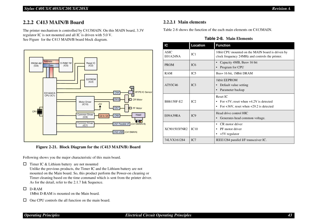
The printer mechanism is controlled by C413MAIN. On this MAIN board, 3.3V regulator IC is not mounted and all IC is driven with 5.0 V.
See Figure for the C413 MAIN/B board block diagram.
PROM 4M | Address | Reset IC |
|
|
| |
|
|
|
| |||
(IC6) | Data | (IC5) | (IC2) |
|
|
|
|
|
| EEPROM |
|
|
|
|
|
| (IC3) |
|
|
|
| E01A24CA |
|
|
| CN4 | HP/PE/IC Sensor |
| CPU (IC1) |
|
|
|
|
|
|
|
| Motor Driver |
| CN12 | CR Motor |
|
|
| +5V |
|
| |
|
|
| (IC10) |
|
| |
|
|
|
|
| CN7 | PF Motor |
CR1 |
|
|
|
|
|
|
|
|
| Common Driver | Q2 & Q3 | CN9 | Head |
|
|
| (IC9) |
| ||
|
|
|
|
|
| |
|
|
| Common Driver |
| CN7 Parallel I/F | |
|
|
| (IC7) |
| ||
|
|
|
|
|
| |
|
|
|
|
| CN3 USB (C413MAIN) | |
Figure 2-21. Block Diagram for the (C413 MAIN/B) Board
Following shows you the major characteristic of this main board.
Timer IC & Lithium battery are not mounted
Unlike the previous products, the Timer IC and the Lithium battery are not mounted on the Main board. So, this product perform the
D-RAM
1Mbit
One CPU controls the all function on the main board.
2.2.2.1 Main elements
Table
Table 2-8. Main Elements
IC | Location | Function | ||
|
|
| ||
ASIC | IC1 | 16bit CPU mounted on the MAIN board is driven by | ||
E01A24NA | clock frequency 24MHz and controls the printer. | |||
| ||||
|
|
| ||
PROM | IC6 | • Capacity 4MB, Bus= 16 bit | ||
• | Program for CPU | |||
|
| |||
RAM | IC5 | Bus= 16 bit, 1Mbit DRAM | ||
|
|
| ||
|
| 1kbit EEPROM | ||
AT93C46 | IC3 | • | Default value setting | |
|
| • | Parameter backup | |
|
|
| ||
|
| Reset IC | ||
IC2 | • | For +5V; reset when +4.2V is detected | ||
|
| • For +36V, reset when +29.2 is detected | ||
|
|
| ||
E09A39RA | IC9 | Head drive control HIC | ||
• Generates head common voltage. | ||||
|
| |||
|
|
|
| |
|
| • | CR motor driver | |
XC901503FNR2 | IC10 | • | PF motor driver | |
|
| • | +5V regulator | |
|
|
| ||
74LVX161284 | IC7 | IEEE1284 parallel I/F transceiver IC. | ||
|
|
|
| |
Operating Principles | Electrical Circuit Operating Principles | 43 |