Stylus C40UX/C40SX/C20UX/C20SX | Revision A |
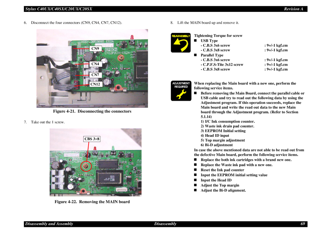
6.Disconnect the four connectors (CN9, CN4, CN7, CN12).
![]()
![]() CN9
CN9
![]()
![]()
![]() CN4
CN4
![]()
![]()
![]() CN7
CN7
8.Lift the MAIN board up and remove it.
Tightening Torque for screw
| USB Type |
|
| - C.B.S 3x6 screw | : |
| - C.B.S 3x8 screw | : |
| Parallel Type |
|
| - C.B.S 3x6 screw | : |
| - | : |
| - C.B.S 3x8 screw | : |
![]() CN12
CN12
Figure 4-21. Disconnecting the connectors
7.Take out the 1 screw.
CBS 3⋅ 8
Figure 4-22. Removing the MAIN board
ADJUSTMENT REQUIRED
When replacing the Main board with a new one, perform the following service items.
Before removing the Main Board, connect the parallel cable or USB cable and try to read out the following data by using the Adjustment program. If this operation succeeds, replace the Main board and write the read out data to the new Main board through the Adjustment program. (Refer to Section 5.1.14)
1)I/C Ink consumption counter.
2)Waste ink drain pad counter.
3)EEPROM Initial setting
4)Head ID input
5)Top margin adjustment
6)
In case the above mentioned data are not able to be read out from the defective Main board, perform the following service items.
Replace the both ink cartridges with a brand new one.
Replace the Waste ink pad with a new one.
Reset the Ink pad counter
Input the EEPROM initial setting value
Input the Head ID
Adjust the Top margin
Adjust the
Disassembly and Assembly
Disassembly | 69 |