Setup & Operation 2. Specifications
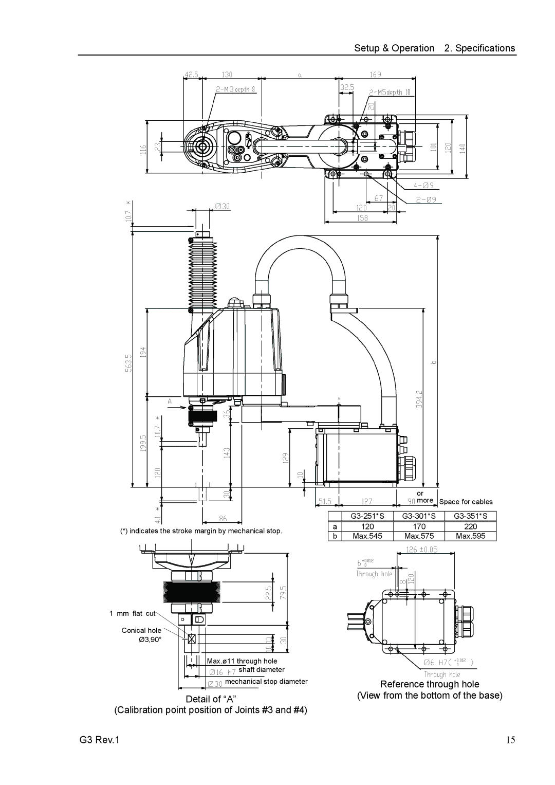
(*) indicates the stroke margin by mechanical stop.
1 mm flat cut
Conical hole Ø3,90°
Max.ø11 through hole shaft diameter
mechanical stop diameter
Detail of “A”
(Calibration point position of Joints #3 and #4)
G3 Rev.1
|
| or |
|
|
|
| more | Space for cables | |
|
|
|
|
|
|
| |||
a | 120 | 170 |
| 220 |
b | Max.545 | Max.575 |
| Max.595 |
Reference through hole
(View from the bottom of the base)
15