Setup & Operation 2. Specifications
2.3.2Multiple Mounting
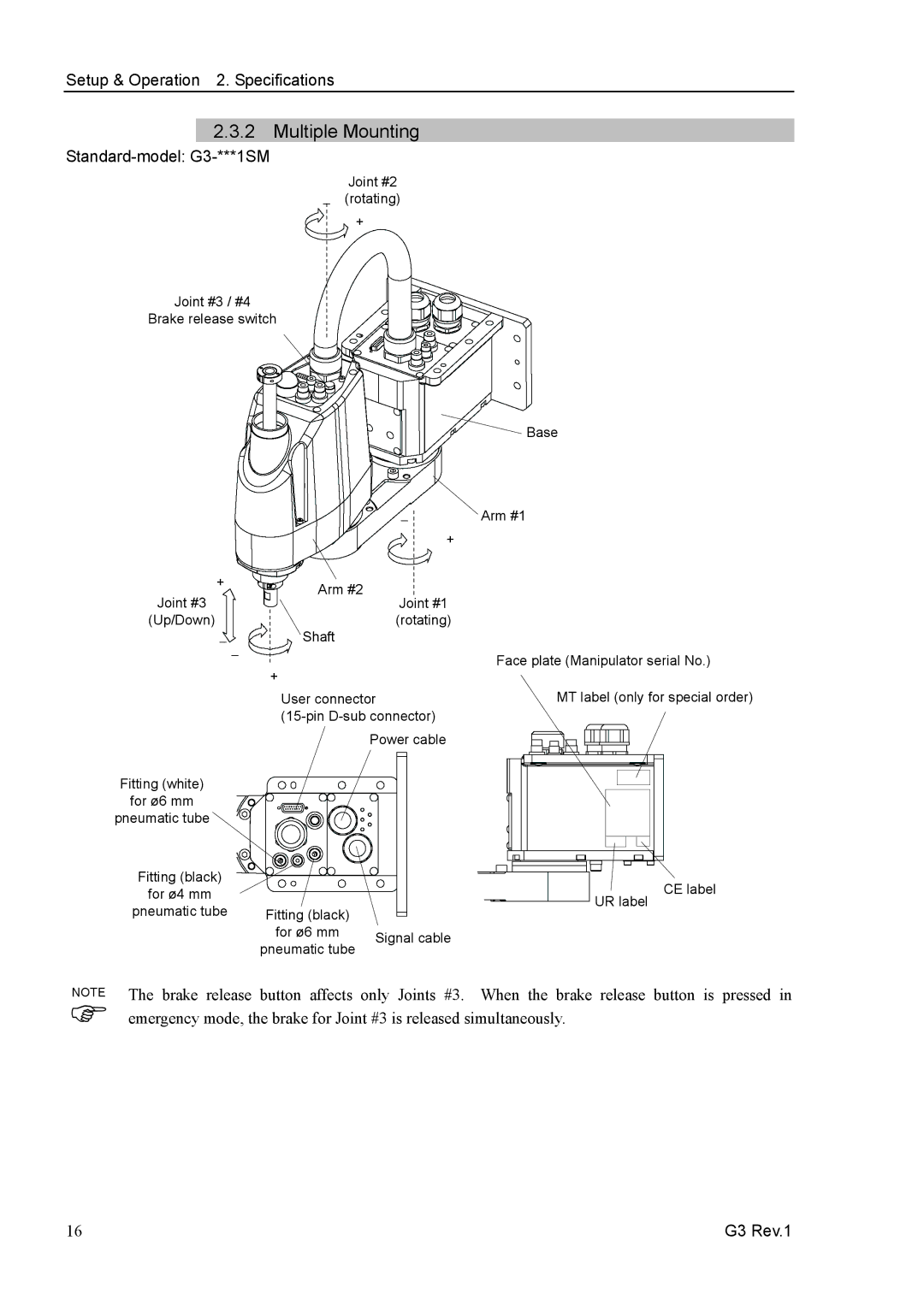
Standard-model: G3-***1SM
Joint #2
−(rotating)
+
Joint #3 / #4
Brake release switch
|
|
| Base |
|
| − | Arm #1 |
|
| + |
|
+ | Arm #2 |
|
|
Joint #3 | Joint #1 |
| |
|
| ||
(Up/Down) | Shaft | (rotating) |
|
− − |
| Face plate (Manipulator serial No.) | |
| + |
| |
|
|
| |
| User connector | MT label (only for special order) | |
|
| ||
|
| Power cable |
|
Fitting (white) |
|
|
|
for ø6 mm |
|
|
|
pneumatic tube |
|
|
|
Fitting (black) |
|
| CE label |
for ø4 mm |
|
| |
|
| UR label | |
pneumatic tube | Fitting (black) |
| |
|
| ||
| for ø6 mm | Signal cable |
|
| pneumatic tube |
| |
|
|
| |
NOTE | button affects only Joints #3. | When the brake release button is pressed in | |
The brake release | |||
) emergency mode, the brake for Joint #3 is released simultaneously.
16 | G3 Rev.1 |