Setup & Operation 3. Environments and Installation
3.7 User Wires and Pneumatic Tubes
■Only authorized or certified personnel should be allowed to perform wiring. Wiring by unauthorized or uncertified personnel may result in bodily injury and/or
CAUTION | malfunction of the robot system. |
| |
| User electrical wires and pneumatic tubes are contained in the cable unit. |
Electrical Wires
Rated Voltage | Allowable | Wires | |
Current | |||
|
| ||
AC/DC30 V | 1 A | 15 | |
|
|
|
Nominal Sectional Area | Outer Diameter | Note |
0.211 mm2 |
|
|
ø8.3±0.3 mm | Shielded |
Maker
Standard
15 pin
Suitable Connector | JAE | (Solder type) | |
Clamp Hood | JAE | (Connector setscrew: |
Pins with the same number, indicated on the connectors on both ends of the cables, are connected.
Pneumatic Tubes
Max. Usable Pneumatic Pressure Pneumatic Tubes
Outer Diameter × Inner Diameter
0.59 MPa (6 kgf/cm2 : 86 psi)
2 | ø6 mm ⋅ ø4 mm |
1 | ø4 mm ⋅ ø2.5 mm |
Fittings for ø6 mm and ø4 mm (outer diameter) pneumatic tubes are supplied on both ends of the pneumatic tubes.
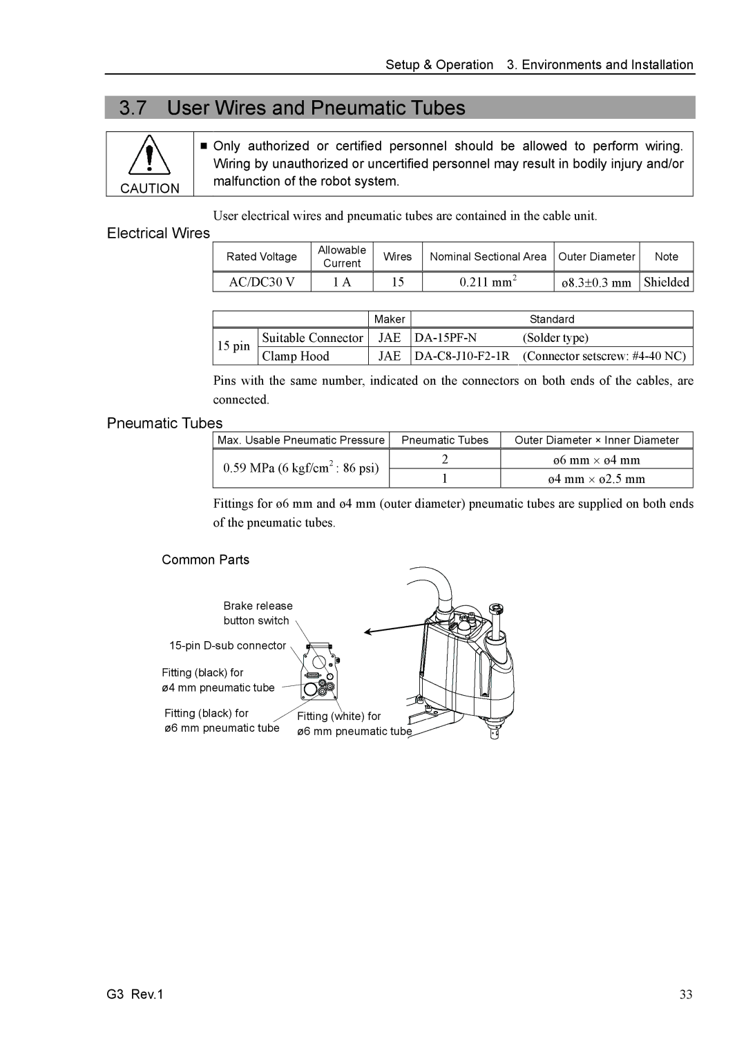
Common Parts
Brake release button switch
| |
Fitting (black) for |
|
ø4 mm pneumatic tube |
|
Fitting (black) for | Fitting (white) for |
ø6 mm pneumatic tube | ø6 mm pneumatic tube |
G3 Rev.1 | 33 |