| Maintenance 3. Covers | |
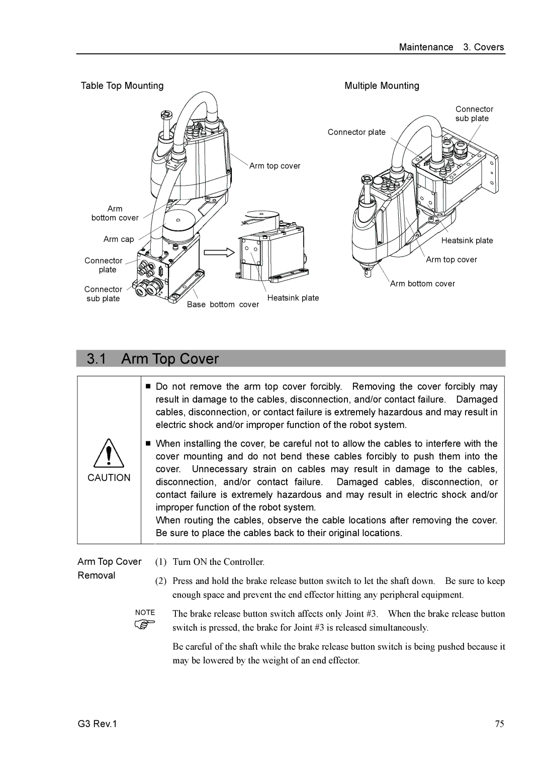
Table Top Mounting | Multiple Mounting | |
| Connector | |
| sub plate | |
| Connector plate | |
| Arm top cover | |
Arm |
| |
bottom cover |
| |
Arm cap | Heatsink plate | |
Connector | Arm top cover | |
plate |
| |
Connector | Arm bottom cover | |
Base bottom cover Heatsink plate | ||
sub plate |
3.1 Arm Top Cover
CAUTION
■Do not remove the arm top cover forcibly. Removing the cover forcibly may result in damage to the cables, disconnection, and/or contact failure. Damaged cables, disconnection, or contact failure is extremely hazardous and may result in electric shock and/or improper function of the robot system.
■When installing the cover, be careful not to allow the cables to interfere with the cover mounting and do not bend these cables forcibly to push them into the cover. Unnecessary strain on cables may result in damage to the cables, disconnection, and/or contact failure. Damaged cables, disconnection, or contact failure is extremely hazardous and may result in electric shock and/or improper function of the robot system.
When routing the cables, observe the cable locations after removing the cover. Be sure to place the cables back to their original locations.
Arm Top Cover (1) | Turn ON the Controller. | |
Removal | (2) | Press and hold the brake release button switch to let the shaft down. Be sure to keep |
| ||
enough space and prevent the end effector hitting any peripheral equipment.
NOTE
)
The brake release button switch affects only Joint #3. When the brake release button switch is pressed, the brake for Joint #3 is released simultaneously.
Be careful of the shaft while the brake release button switch is being pushed because it may be lowered by the weight of an end effector.
G3 Rev.1 | 75 |