Setup & Operation 5. Motion Range
5.2.1Setting the Mechanical Stops of Joints #1 and #2
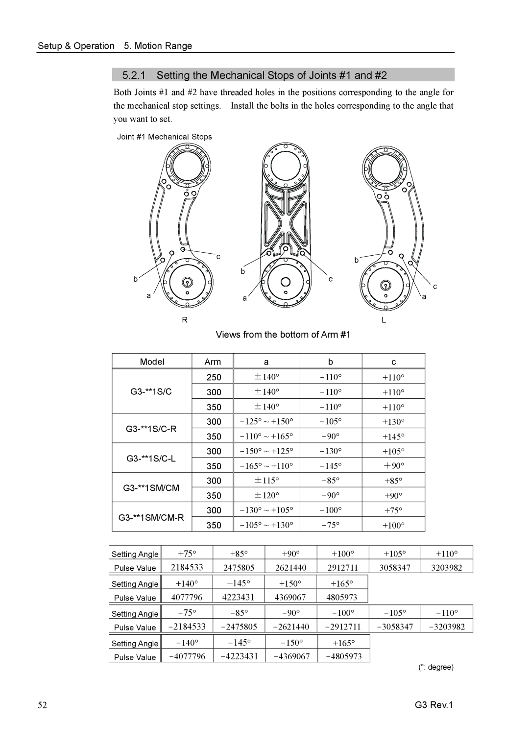
Both Joints #1 and #2 have threaded holes in the positions corresponding to the angle for the mechanical stop settings. Install the bolts in the holes corresponding to the angle that you want to set.
Joint #1 Mechanical Stops
|
|
| R |
|
|
|
|
|
|
|
|
|
|
| L |
|
|
| |
|
|
|
|
|
| Views from the bottom of Arm #1 |
|
|
|
|
| ||||||||
|
|
|
|
|
|
|
|
|
|
|
|
|
|
|
|
|
|
| |
| Model |
| Arm |
|
| a |
| b |
| c |
|
|
| ||||||
|
| 250 |
| ±140° |
| +110° |
|
|
| ||||||||||
|
| 300 |
| ±140° |
| ° | ° |
|
|
| |||||||||
|
|
|
|
|
|
|
|
|
|
|
| +110 |
|
|
| ||||
|
|
|
|
| 350 |
| ±140° |
| +110° |
|
|
| |||||||
|
| 300 |
|
| +130° |
|
|
| |||||||||||
|
| 350 |
|
| +145° |
|
|
| |||||||||||
|
|
|
|
|
|
|
|
|
| ||||||||||
|
| 300 |
|
| +105° |
|
|
| |||||||||||
|
| 350 |
|
|
| +90° |
|
|
| ||||||||||
|
|
|
|
|
|
|
|
|
|
| |||||||||
|
| 300 |
| ±115° |
| +85° |
|
|
| ||||||||||
|
| 350 |
| ±120° |
| +90° |
|
|
| ||||||||||
|
|
|
|
|
|
|
|
|
| ||||||||||
|
| 300 |
|
| +75° |
|
|
| |||||||||||
|
| 350 |
|
| +100° |
|
|
| |||||||||||
|
|
|
|
|
|
|
|
|
| ||||||||||
|
|
|
|
|
|
|
|
|
|
|
|
|
|
| |||||
Setting Angle |
| +75° |
|
| +85° |
|
| +90° | +100° |
| +105° |
| +110° | ||||||
| Pulse Value |
| 2184533 |
|
| 2475805 |
|
| 2621440 | 2912711 |
| 3058347 |
| 3203982 | |||||
|
|
|
|
|
|
|
|
|
|
|
|
|
|
| |||||
Setting Angle |
| +140° |
|
| +145° |
| +150° | +165° |
|
|
|
|
| ||||||
| Pulse Value |
| 4077796 |
|
| 4223431 |
| 4369067 | 4805973 |
|
|
|
|
| |||||
|
|
|
|
|
|
|
|
|
|
| |||||||||
Setting Angle |
|
|
|
|
|
| |||||||||||||
| Pulse Value |
|
|
|
|
| |||||||||||||
|
|
|
|
|
|
|
|
|
|
|
|
| |||||||
Setting Angle |
|
|
|
| +165° |
|
|
|
|
| |||||||||
| Pulse Value |
|
|
|
|
| (°: degree) | ||||||||||||
|
|
|
|
|
|
|
|
|
|
|
|
|
|
|
|
| |||
52 | G3 Rev.1 |