15 Ethernet interface
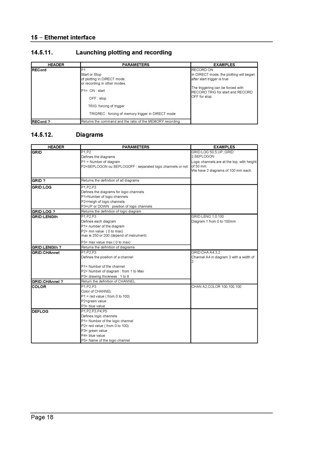
14.5.11.Launching plotting and recording
HEADER | PARAMETERS | EXAMPLES |
RECord | P1 | RECORD ON |
| Start or Stop | In DIRECT mode, the plotting will began |
| of plotting in DIRECT mode, | after start trigger is true |
| or recording in other modes. | The triggering can be forced with |
| P1= ON : start | |
| RECORD TRIG for start and RECORD | |
|
| |
| OFF : stop | OFF for stop |
|
| |
| TRIG: forcing of trigger |
|
| TRIGREC : forcing of memory trigger in DIRECT mode |
|
|
|
|
RECord ? | Returns the command and the ratio of the MEMORY recording |
|
14.5.12.Diagrams
HEADER | PARAMETERS | EXAMPLES |
GRID | P1,P2 | GRID:LOG 50,5,UP;:GRID |
| Defines the diagrams | 2,SEPLOGON |
| P1 = Number of diagram | Logic channels are at the top, with height |
| P2=SEPLOGON ou SEPLOGOFF : separated logic channels or not | of 50 mm. |
|
| We have 2 diagrams of 100 mm each. |
|
|
|
GRID ? | Returns the definition of all diagrams |
|
|
|
|
GRID:LOG | P1,P2,P3 |
|
| Defines the diagrams for logic channels |
|
| P1=Number of logic channels |
|
| P2=Heigh of logic channels |
|
| P3=UP or DOWN : position of logic channels |
|
GRID:LOG ? | Returns the definition of logic diagram |
|
GRID:LENGth | P1,P2,P3 | GRID:LENG 1,0,100 |
| Defines each diagram | Diagram 1 from 0 to 100mm |
| P1= number of the diagram |
|
| P2= min value ( 0 to max) |
|
| max is 250 or 200 (depend of instrument) |
|
| P3= max value max ( 0 to max) |
|
GRID:LENGth ? | Returns the definition of diagrams |
|
GRID:CHAnnel | P1,P2,P3 | GRID:CHA A4,3,2 |
| Defines the position of a channel | Channel A4 in diagram 3 with a width of |
|
| 2 |
| P1= Number of the channel |
|
| P2= Number of diagram : from 1 to Max |
|
| P3= drawing thickness : 1 to 8 |
|
GRID:CHAnnel ? | Return the definition of CHANNEL |
|
COLOR | P1,P2,P3 | CHAN A2,COLOR 100,100,100 |
| Color of CHANNEL |
|
| P1 = red value ( from 0 to 100) |
|
| P2=green value |
|
| P3= blue value |
|
DEFLOG | P1,P2,P3,P4,P5 |
|
| Defines logic channels |
|
| P1= Number of the logic channel |
|
| P2= red value ( from 0 to 100) |
|
| P3= green value |
|
| P4= blue value |
|
| P5= Name of the logic channel |
|
Page 18
