15 Ethernet interface
*ESR ? INTERROGATION OF THE CONTENT OF THE STATUS REGISTER OF THE STANDARD EVENTS OF AN APPLIANCE
answer by the appliance: NR1 number between 0 and 255.
All the events are deleted and the register is reset to zero (see the following paragraph).
*SRE VALIDATION OF THE SERVICE REQUEST OF AN APPLIANCE *SRE is followed by a number between 0 and 63 or between 128 and 191.
action: the appliance modifies the validation register of the service requests (see the following paragraph).
*SRE ? INTERROGATION OF THE VALIDATION REGISTER OF THE SERVICE REQUEST OF AN APPLIANCE
answer by the appliance: NR1 number between 0 and 63 or between 128 and 191 (see the following paragraph).
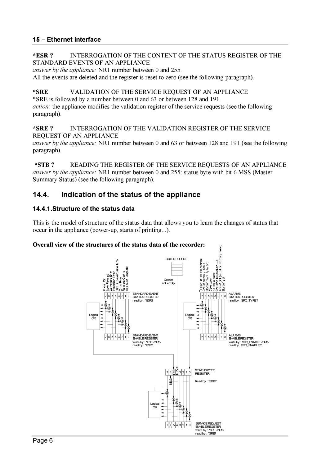
*STB ? READING THE REGISTER OF THE SERVICE REQUESTS OF AN APPLIANCE answer by the appliance: NR1 number between 0 and 255: status byte with bit 6 MSS (Master Summary Status) (see the following paragraph).
14.4.Indication of the status of the appliance
14.4.1.Structure of the status data
This is the model of structure of the status data that allows you to learn the changes of status that occur in the appliance
Overall view of the structures of the status data of the recorder:
OUTPUT QUEUE
|
| Queue |
| |
|
| not empty |
| |
| 7 6 5 4 3 2 1 0 | STANDARD EVENT |
| 7 6 5 4 3 2 1 0 |
| STATUSREGISTER |
| ||
|
| read by : *ESR? |
|
|
| & |
|
| & |
| & |
|
| & |
Logical | & |
| Logical | & |
& |
| & | ||
OR | & |
| OR | & |
| & |
|
| & |
| & |
|
| & |
| & |
|
| & |
| 7 6 5 4 3 2 1 0 | STANDARDEVENT |
| 7 6 5 4 3 2 1 0 |
| ENABLEREGISTER |
| ||
|
| w rite by : *ESE<NRf> |
|
|
|
| read by : *ESE? |
|
|
|
| 7 6 | 3 2 1 0 | STATUSBYTE |
|
| REGISTER | ||
|
|
|
| |
|
|
|
| Read by : *STB? |
|
| & |
|
|
|
|
| & |
|
|
| Logical | & |
|
|
| OR | & |
|
|
| & |
| |
|
|
|
| |
|
|
| & |
|
|
|
| & |
|
|
| 7 | 5 4 3 2 1 0 | SERVICEREQUEST |
|
| ENABLEREGISTER | ||
|
|
|
| |
|
|
|
| write by : *SRE<NRf> |
|
|
|
| read by : *SRE? |
ALARMS STATUSREGISTER read by : SRQ_TYPE?
ALARMS ENABLEREGISTER
write by : SRQ_ENABLE<NRf>
read by : SRQ_ENABLE?
Page 6
