14 Inputs / Outputs
14.2.Logical inputs
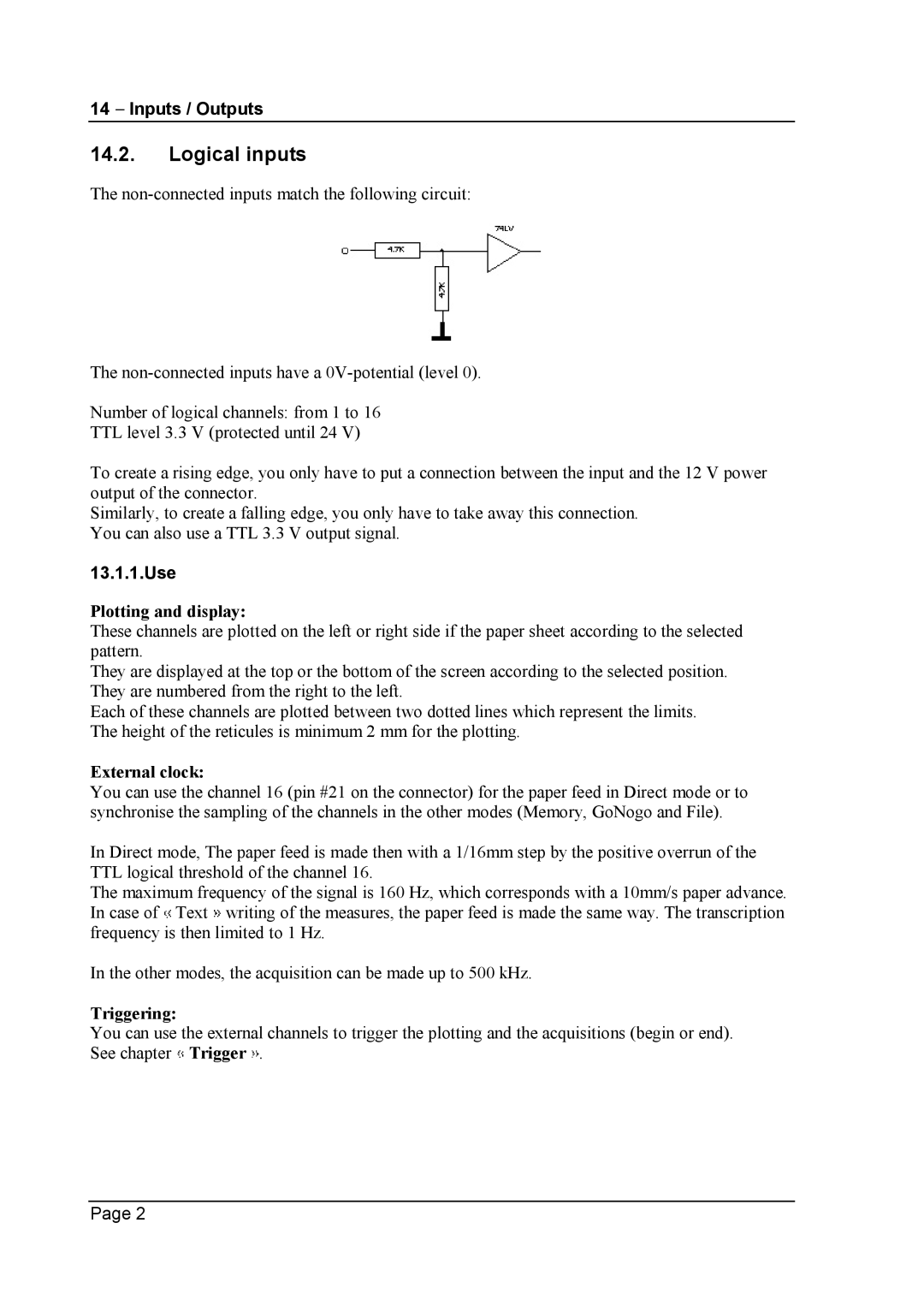
The
The
Number of logical channels: from 1 to 16
TTL level 3.3 V (protected until 24 V)
To create a rising edge, you only have to put a connection between the input and the 12 V power output of the connector.
Similarly, to create a falling edge, you only have to take away this connection. You can also use a TTL 3.3 V output signal.
13.1.1.Use
Plotting and display:
These channels are plotted on the left or right side if the paper sheet according to the selected pattern.
They are displayed at the top or the bottom of the screen according to the selected position. They are numbered from the right to the left.
Each of these channels are plotted between two dotted lines which represent the limits. The height of the reticules is minimum 2 mm for the plotting.
External clock:
You can use the channel 16 (pin #21 on the connector) for the paper feed in Direct mode or to synchronise the sampling of the channels in the other modes (Memory, GoNogo and File).
In Direct mode, The paper feed is made then with a 1/16mm step by the positive overrun of the TTL logical threshold of the channel 16.
The maximum frequency of the signal is 160 Hz, which corresponds with a 10mm/s paper advance. In case of ![]() Text
Text ![]() writing of the measures, the paper feed is made the same way. The transcription frequency is then limited to 1 Hz.
writing of the measures, the paper feed is made the same way. The transcription frequency is then limited to 1 Hz.
In the other modes, the acquisition can be made up to 500 kHz.
Triggering:
You can use the external channels to trigger the plotting and the acquisitions (begin or end). See chapter ![]() Trigger
Trigger ![]() .
.
Page 2