FCD/DVD drive — Insert any compatible CD or DVD into this drive. This drive is used for system updates or software installation.
G3.5 inch floppy drive — This drive accepts 3.5 inch floppy disks.
Rear Panel Features
NOTE: | Some features listed in this user guide may not be available on all units. This will |
not affect the overall functionality of the VNM Recorder. | |
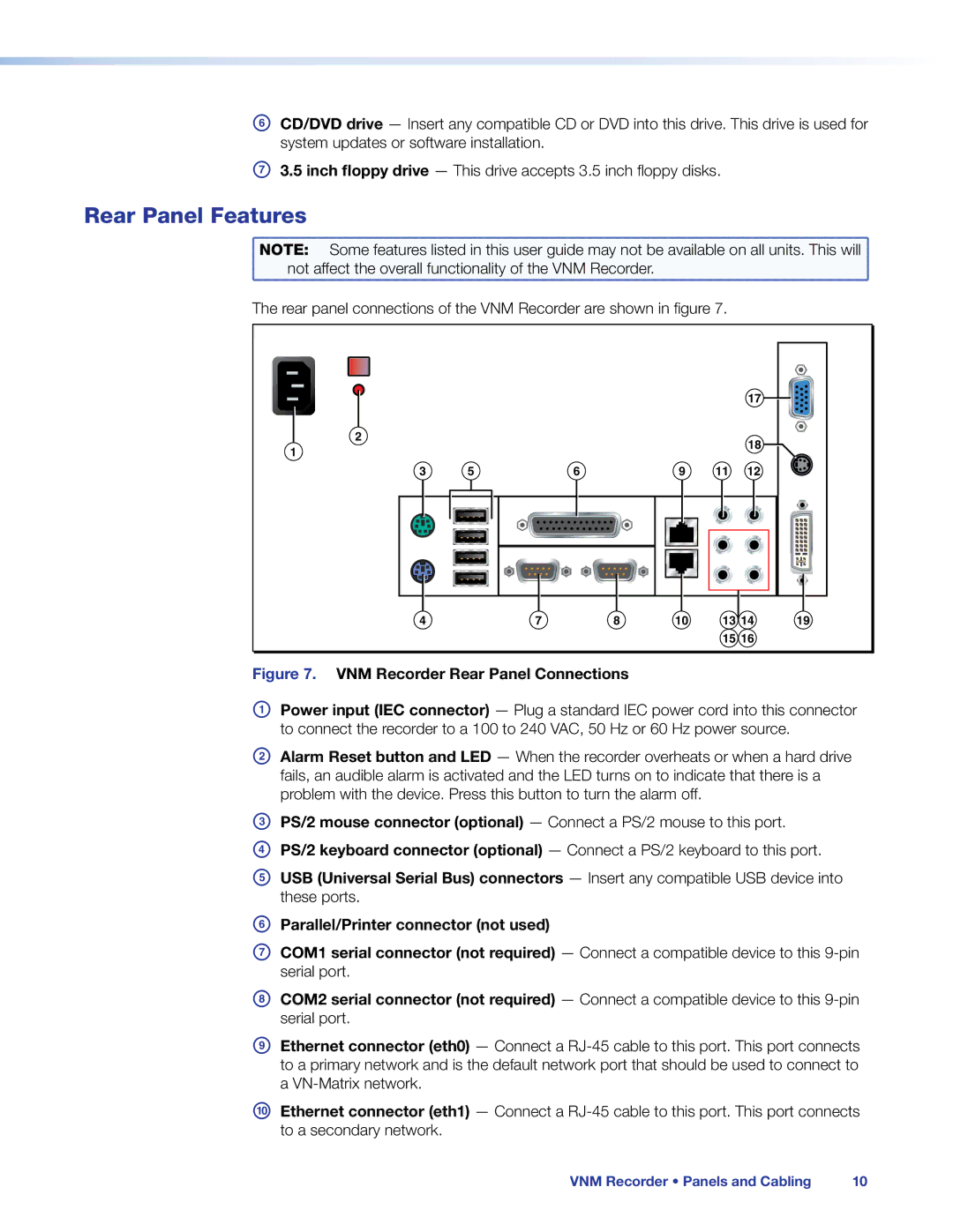
The rear panel connections of the VNM Recorder are shown in figure 7.
17 ![]()
![]()
2 |
|
|
|
|
|
| 18 |
1 |
|
|
|
|
|
| |
|
|
|
|
|
|
| |
3 | 5 | 6 | 9 | 11 | 12 | ||
|
|
|
|
|
|
|
|
|
|
|
|
|
|
|
|
|
|
|
|
|
|
|
|
|
|
|
|
|
|
|
|
|
|
|
|
|
|
|
|
|
|
|
|
|
|
|
|
|
|
|
|
|
|
|
|
4 | 7 | 8 | 10 | 13 14 | 19 |
|
|
|
| 15 16 |
|
Figure 7. VNM Recorder Rear Panel Connections
APower input (IEC connector) — Plug a standard IEC power cord into this connector to connect the recorder to a 100 to 240 VAC, 50 Hz or 60 Hz power source.
BAlarm Reset button and LED — When the recorder overheats or when a hard drive fails, an audible alarm is activated and the LED turns on to indicate that there is a problem with the device. Press this button to turn the alarm off.
CPS/2 mouse connector (optional) — Connect a PS/2 mouse to this port.
DPS/2 keyboard connector (optional) — Connect a PS/2 keyboard to this port.
EUSB (Universal Serial Bus) connectors — Insert any compatible USB device into these ports.
FParallel/Printer connector (not used)
GCOM1 serial connector (not required) — Connect a compatible device to this
HCOM2 serial connector (not required) — Connect a compatible device to this
IEthernet connector (eth0) — Connect a
JEthernet connector (eth1) — Connect a
VNM Recorder • Panels and Cabling | 10 |
