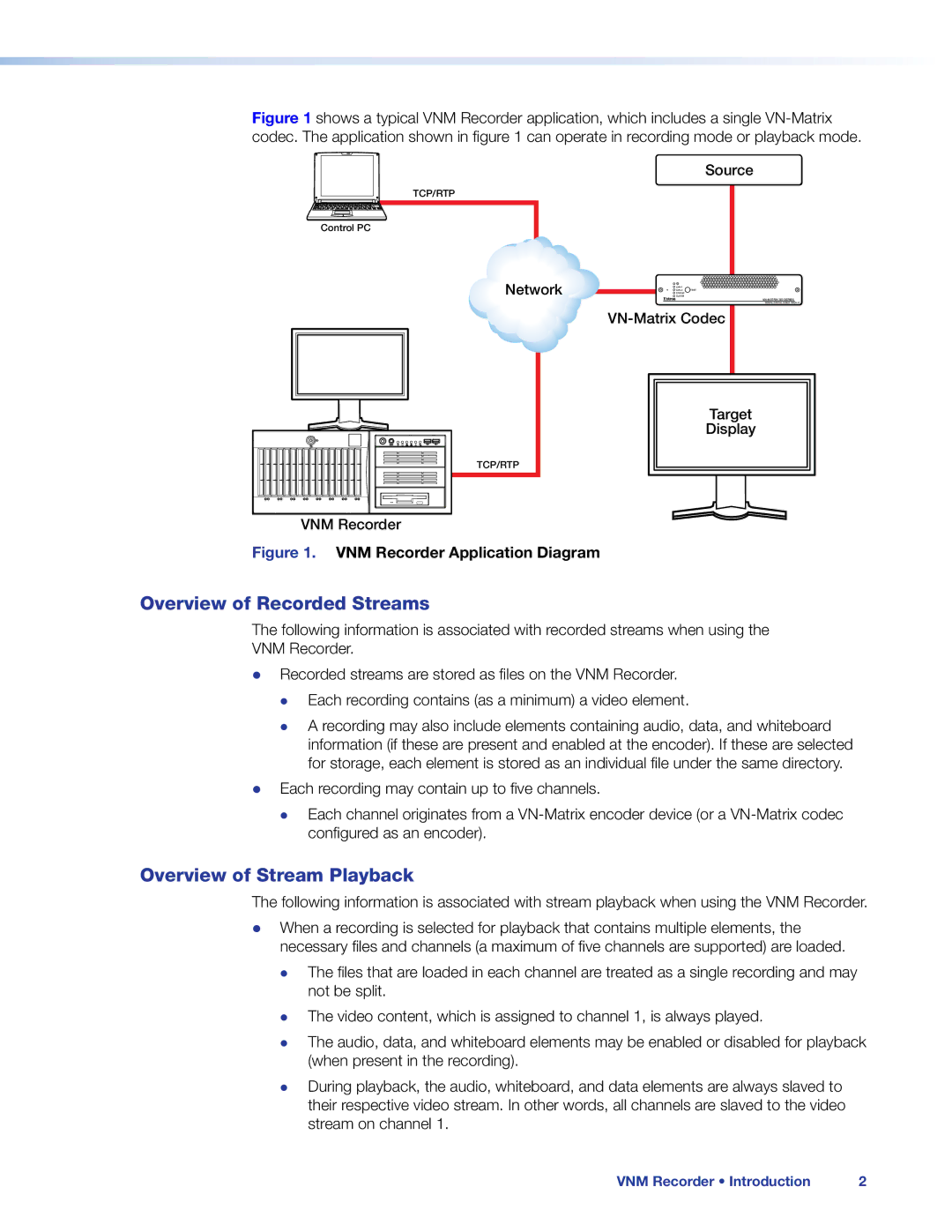
Figure 1 shows a typical VNM Recorder application, which includes a single VN-Matrix codec. The application shown in figure 1 can operate in recording mode or playback mode.
Source
TCP/RTP
Control PC
Network
![]()
![]()
![]() STATUS
STATUS
![]() ALARM
ALARM
Target
Display
TCP/RTP
VNM Recorder
Figure 1. VNM Recorder Application Diagram
Overview of Recorded Streams
The following information is associated with recorded streams when using the VNM Recorder.
zz Recorded streams are stored as files on the VNM Recorder. zz Each recording contains (as a minimum) a video element.
zz A recording may also include elements containing audio, data, and whiteboard information (if these are present and enabled at the encoder). If these are selected for storage, each element is stored as an individual file under the same directory.
zz Each recording may contain up to five channels.
zz Each channel originates from a
Overview of Stream Playback
The following information is associated with stream playback when using the VNM Recorder.
zz When a recording is selected for playback that contains multiple elements, the necessary files and channels (a maximum of five channels are supported) are loaded.
zz The files that are loaded in each channel are treated as a single recording and may not be split.
zz zz
The video content, which is assigned to channel 1, is always played.
The audio, data, and whiteboard elements may be enabled or disabled for playback (when present in the recording).
zz During playback, the audio, whiteboard, and data elements are always slaved to their respective video stream. In other words, all channels are slaved to the video stream on channel 1.
VNM Recorder • Introduction | 2 |