USP 507 specifications
Extron Electronics has long been a leader in the field of professional AV system design, and one of their standout products is the USP 507. The USP 507 is an advanced universal speaker processor that is engineered to elevate audio performance across a variety of applications. Designed for both commercial and residential environments, the USP 507 combines cutting-edge technology with user-friendly features to deliver superior sound quality and precise audio control.One of the main features of the USP 507 is its comprehensive signal processing capabilities. The device supports a range of audio formats and delivers 48 kHz or 96 kHz sample rates, ensuring high fidelity in audio reproduction. It also includes a configurable 5-band equalizer per channel, allowing users to fine-tune audio output to accommodate different room acoustics and speaker types.
The USP 507 is equipped with Extron’s patented SpeedMatch technology to enhance speaker performance and optimize audio clarity. This innovative technology automatically analyzes the audio signals and adjusts various parameters to compensate for environmental conditions, ensuring consistent sound quality across all outputs.
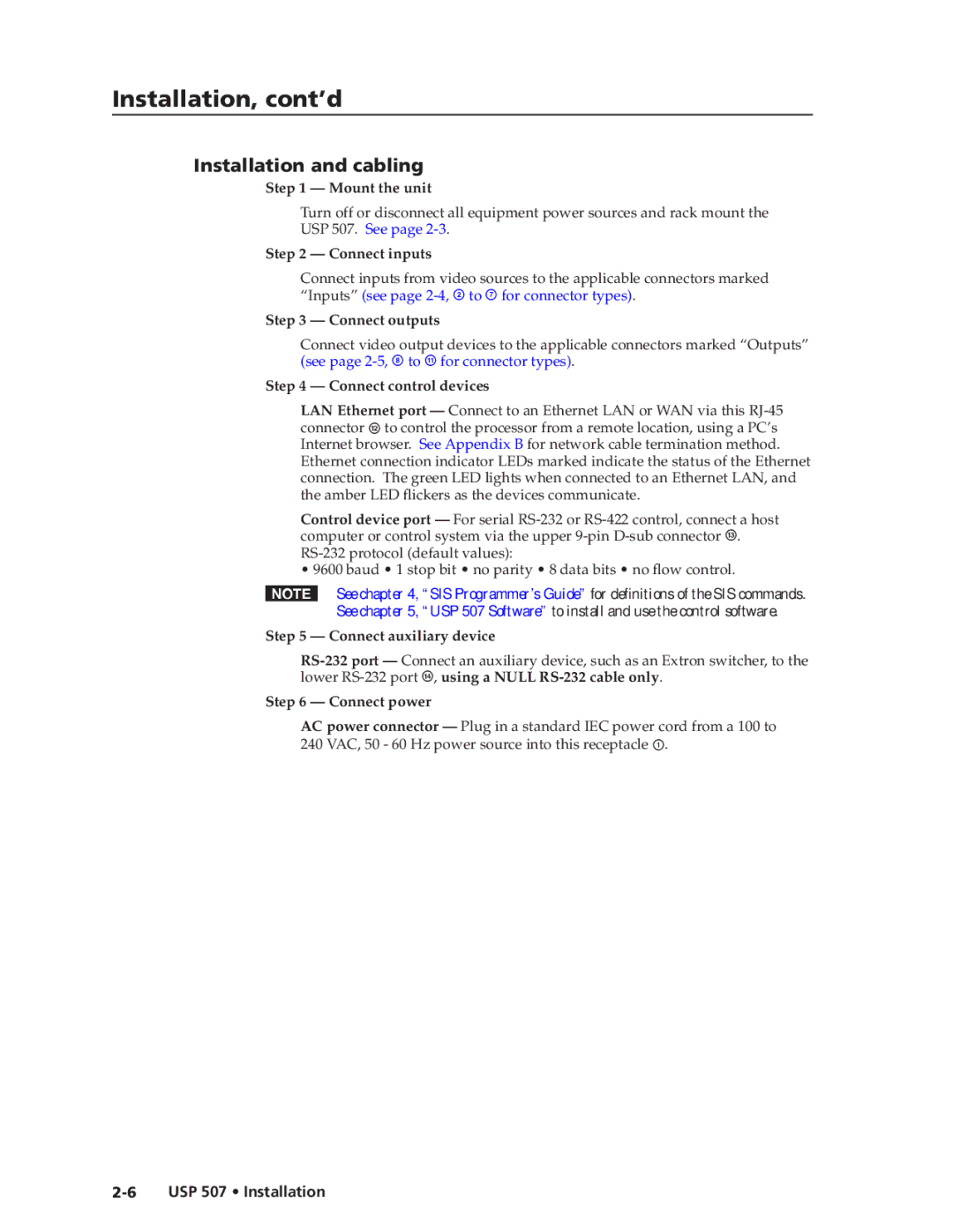
In terms of connectivity, the USP 507 offers a wide array of input and output options. It includes both balanced and unbalanced audio inputs to facilitate seamless integration with other audio equipment. Furthermore, the device provides multiple output zones, enabling simultaneous audio distribution to different areas within a facility.
The USP 507 features intuitive software for simplified setup and operation. The Extron Toolbelt application allows users to configure, manage, and monitor the speaker processor through an easy-to-navigate interface. This software enhances user experience by providing real-time diagnostics and seamless integration with other Extron devices.
Durability and reliability are also hallmarks of the USP 507. Built with high-quality materials, it is designed to withstand the demands of professional use while ensuring long-lasting performance. Additionally, the device comes equipped with advanced thermal management features to prevent overheating during extended operations.
In summary, the Extron USP 507 is a versatile universal speaker processor that combines advanced signal processing technologies, a user-friendly interface, and robust construction. Its ability to deliver superior audio performance makes it an ideal choice for various applications, ranging from corporate environments to high-end residential setups. With its comprehensive features and reliable performance, the USP 507 stands out as an essential tool for audio professionals seeking to enhance their sound experience.
