Page
00080834300
Safety Instructions
Furuno agent or dealer
About the TFT LCD
Table of Contents
Video Pilot Display Navigation Data Display
External Event Mark Target Mark Lines
11.9 Memory Capacity
Chart Symbols, Contour Lines Attributes
12.1 Preventive Maintenance 12-1 12.2
Time Differences Geodetic Chart List
Word to Furuno GD-3300/GP-3300 Owners
Foreword
Vii
Features
Viii
Menu Tree
GPS Antenna Unit GPA-017S
System Configuration
Control Description
Operational Overview
Control description
Inserting Chart Cards
Turning the power on
Turning the Power On/Off
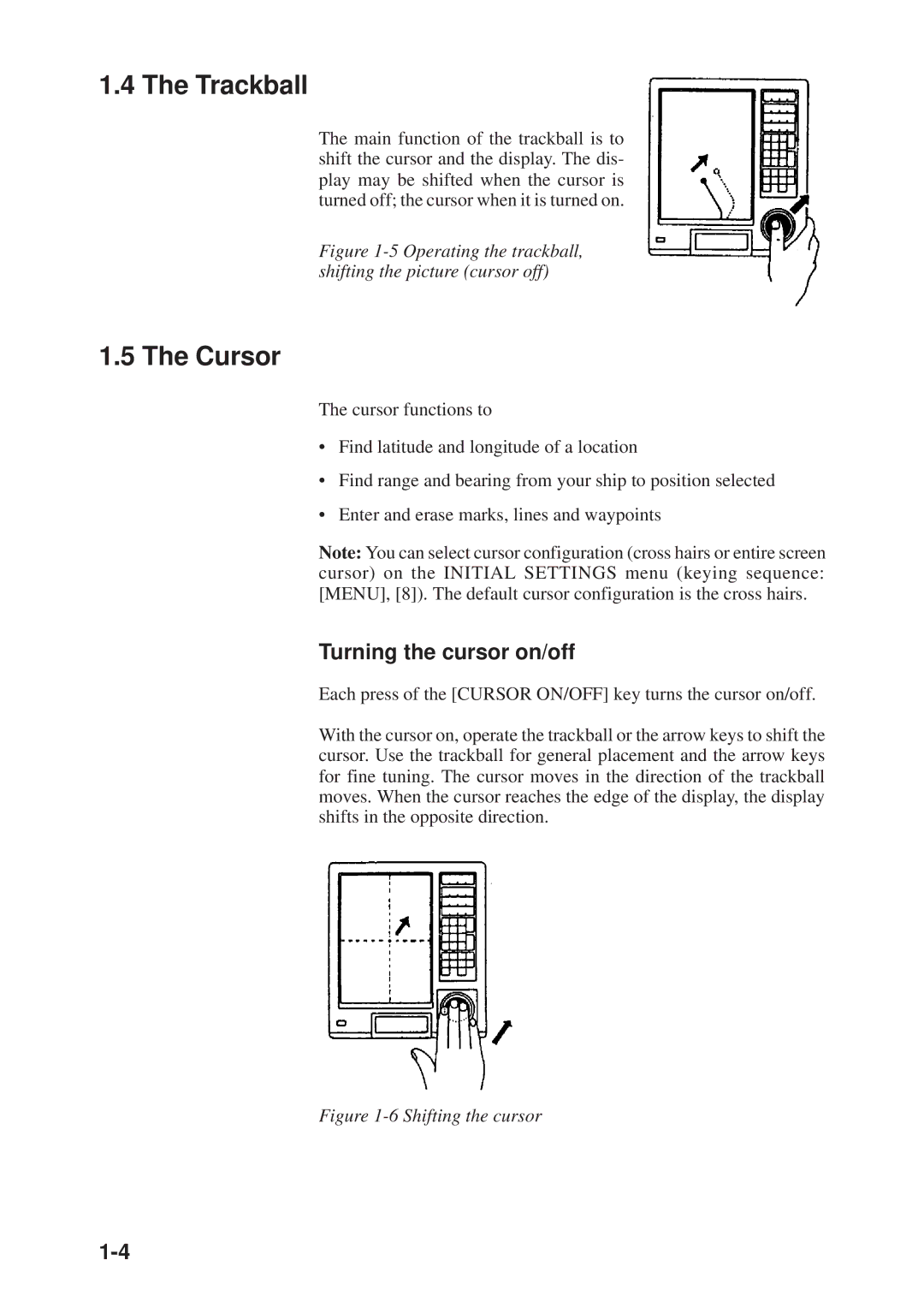
Trackball
Cursor
Turning the cursor on/off
+36 44.257’ N
Shifting the Display
Returning Own Ship Marker to Screen Center
Cursor information
Selecting Screen Center by Cursor Position
How to select screen center
Display Brilliance and Key Backlighting
Chart Scale
Card drives
Card Drives, Chart Cards
Displaying an electronic chart with the power turned on
Insert chart card label side up in the lower slot
Press the eject button
Ejecting the chart card
Chart card troubleshooting
Care and handling of the cards
Chart icons
Furuno chart symbols
Table below shows Furuno chart symbols and their meanings
Buoy, lighthouse data display on Navionics charts
Comparison of FURUNO, Navionics chart cards
Data Window
Data shown when cursor is on
Nav data mode description
Data shown when cursor is off
Plot mode description
Video pilot mode description
Menu operation versus key operation
Menu Operation
Main menu description
Main menu description
Summary of menu operation
Operation on the Display
Selecting options
Entering data
Operational Status Icons
Economy Mode
Plot Mode Displays
Plot display when cursor is on
+36 44.257’ N 140.50 35.92NM 134 40.719’ E
36 44.257’ N
Plot display when cursor is off
22 Initial Settings menu
Setting the Time and Date
Track
Stopping Track Recording
340.5
Track Color
Changing Color, Appearance of Specific Track
Press MENU, 9 and 1 to display the EDIT/TRACK Mark menu
EDIT/TRACK Mark menu
Press MENU, 9, 1 to display the EDIT/TRACK menu
Deleting Track
Deleting track by color
Deleting specific track with cursor, box cursor
Delete Track display
Deleting all track
Plot interval by time or distance
Track Plotting Interval
How the track is drawn
Plot interval and track reconstruction
Setting plot interval 2 to time
Setting plot interval 1 by time
Turning off track display when track is not being recorded
Connecting track after restarting track recording
Customizing the Hold Function
Setup for manually entering plot interval
Tuning off a plot interval
Customizing the Plot Intvl Key
Page
Entering marks at own ship’s position
MARKS, Lines
Entering Marks
Entering marks with the cursor
Press the Mark Color key to show the Change Mark Color menu
Changing Current Mark Color
Changing Shape, Color of Specific Marks
Deleting marks with the cursor
Deleting Marks
Deleting specific marks
Deleting all marks
Erasing an external event mark
External Event Mark
Target Mark
Lines
Entering a line
Changing line color
Deleting lines
Waypoints
Waypoints
Entering Waypoints
Waypoint entry by L/L coordinates
Place the data input cursor on waypoint
Waypoint entry by cursor
Waypoint entry by range and bearing
Waypoint entry at own ship’s position
Waypoint entry by navigation aid
Entering a Comment for a Waypoint
Turning Specific Waypoint Displays On/Off
Deleting waypoints by cursor
Deleting Waypoints
Deleting external waypoint
Setting destination waypoint by cursor
Destination Waypoint
Deleting waypoints through waypoint list
Setting destination waypoint by range and bearing
Setting destination waypoint by waypoint number
11 How a destination waypoint is shown on the display
When you set a destination waypoint
Press the Plot key to display the Data Display
Displaying range and bearing to destination waypoint
36 34.000’ N
134 20.524’ E
Select Cancel from the Dest field Press the ENT key
Cancelling Destination Waypoint
Cancelling destination waypoint through the menu
Cancelling destination waypoint by key input
Sample route
Route Navigation
Creating routes through the route list
Creating Routes
Creating routes with waypoint numbers Menu key
Creating routes with waypoint numbers Route key
Press the Route key to display the Route NO. menu
Creating routes with the cursor
Select WPT no Enter waypoint numbers Press the ENT key
Press the Route to display the Route NO. menu
About route navigation
Following a Route
Temporarily Deselecting a Route Waypoint
Example of when to deselect waypoints
Deleting specific route waypoints
Deleting Route Waypoints
Deleting all route waypoints
Cancelling Route Navigation
10 Route list
Route Calculation
Alarms
Arrival Alarm, Anchor Watch Alarm
Arrival alarm
Alarm range of arrival alarm
Anchor watch alarm
XTE Alarm, Border Alarm
Border alarm
XTE alarm
Press ← twice
Ship’s Speed Alarm
When the Alarm Buzzer Sounds
What alarm is sounding?
Silencing the alarm buzzer
Features
Compares the features of the video pilot and plot displays
Video Pilot Display
Mark data
Destination data
135 21.288’ E
Comparison of plot and video pilot displays
34 44.463’
34 44.463’ N
Navigation Data Display
44 N 135 21 E
Autopilot Data
Features Available with Autopilot Connection
Sample autopilot information on plot display
Autopilot Information on Plot Display
134 40.719’ E 10.0KTS
Autopilot Information on Video Pilot Display
Autopilot in Auto mode
Autopilot in Manual mode
Autopilot on, destination waypoint selected
Autopilot in NAV mode
Memory Card Operations
Formatting Memory Cards
Press the 3 key to select Save Data to Memory Card
Saving Data to Memory Cards
Save Track display
File name example
Playing Back Memory Cards
Press the 5 key to select Display Memory Card
Saving, Playing Back Initial Settings
Saving initial settings
Playing back initial settings
Adding track, marks/lines
Editing Memory Cards
Deleting track, marks/lines from a memory card
Deleting files
10-1
GPS Receiver Operation GP-3300
GPS Information on the Navigation Data Display
GPS receiver status
Satellite schedule
Frequency deviation
10-2
GPS and Dgps Initial Settings
Satellite data
10-3
GPS initial settings menu description
Describes the GPS Initial Settings menu
10-4
Satellite Force Health/Deselection
10-5
Press Menu and 8, and then press − to set the cursor on
10-6
GPS Smoothing
Speed and course GPS smoothing
Latitude and longitude GPS smoothing
10-7
Setting GPS smoothing
10-8
Cold Start
10-9
Selecting chart system
Geodetic Datum
Correcting GPS Position
11-1
Other Functions
Displaying Position in Loran TDs
Displaying position in Loran a TDs
Bearing Display Reference
Displaying position in Loran C TDs
11-2
Magnetic Deviation
Displaying true bearing
11-3
11-4
Changing Chart Appearance
Correcting Chart Position
Correcting chart position by cursor
11-5
Correcting chart position by latitude and longitude
Corrections chart position by Δ Delta L/L
11-6
Cancelling chart position correction
Loran TD Correction
11-7
Calculating R/B Between Two Points
Calculating R/B by latitude and longitude
11-8
11-9
Calculating R/B by waypoint numbers
Memory Capacity
Locking Preferred Settings
Locking or unlocking preferred settings
Default memory arrangement is as shown in Figure
When the track memory becomes full oldest track is deleted
Track memory
11-11
11-12
When the mark memory becomes full no marks can be entered
Apportioning the Memory
Mark/line memory
11-13
Reading Number of Track, Marks Used
11-14
Smoothing
11-15
Selecting Navaid
11-16
Track, Mark and Marker Attributes
Initial settings menu
Special menu
11-17
11-18
Customizable items on the Initial Settings menu
Chart Symbols, Contour Lines Attributes
11-19
Select item and option as appropriate Press the ENT key
Maintenance & Troubleshooting
Preventive Maintenance
12-1
12-2
Diagnostic Tests
Self test at power on
Memory circuits, I/O ports
Keyboard test
12-3
To escape from the test, press any key
Check the pattern for color dropout Press any key to escape
Test pattern 1 color dropout
Test pattern 2 color distortion
12-4
12-5
Error Messages
No files on memory card to delete
12-6
Memory card replaced during operation
No file by that name exists
Replacement of Fuse
12-7
Waypoint being used as destination waypoint
Replacement of Batteries
Memory card battery
12-8
12-9
Verifying Program Version No
Plotter section
GPS section GP-3300
12-10
Troubleshooting Table
12-11
12-12
Clearing Memories
Press the 8 key to select Clear Memory
12-13
Time Differences
Appendix
Adindan
Geodetic Chart List
GD/GP-3300
Specifications of Color Video PLOTTER/COLOR GPS Plotter
Coating Color
Index-1
Index
Index-2
Index-3