By Galil Motion Control, Inc
DMC-3425
Page
Contents
Connecting Hardware
Programming Motion
Application Programming 107
ZOH
DAC
Warranty
J5 Power 6 PIN Molex
Introduction
Overview
Brushless Servo Motor with Sinusoidal Commutation
Standard Servo Motors with +/- 10 Volt Command Signal
Stepper Motor with Step and Direction Signals
Overview of Motor Types
DMC-3425 Overview
Communication
DMC-3425 Functional Elements
Microcomputer Section
Motor Interface
Amplifier Driver
General I/O
System Elements
Motor
Encoder
Watch Dog Timer
DMC-3425 Motion Controller
Getting Started
Elements You Need
Installing the DMC-3425 Controller
Configuring Jumpers on the DMC-3425
Determine Overall Motor Configuration
9600 1200
Setting the Baud Rate on the DMC-3425
Selecting MO as default on the DMC-3425
Stepper Motor Jumpers
A1 A2 A4 A8
Axis Configuration Jumpers
Using Galil Software for DOS
Installing the Communications Software
Using Galil Software for Windows
Getting Started DMC-3425
TPA CR
Using Non-Galil Communication Software
Sending Test Commands to the Terminal
Communicating through the Ethernet
Address
Make connections to amplifier and encoder
Set-up axis for sinusoidal commutation optional
Getting Started DMC-3425
Connect Standard Servo Motor
MO CR
Check the Polarity of the Feedback Loop
TT CR
Inverting the Loop Polarity
SH CR
BG CR
Power Supply
Connect brushless motor for sinusoidal commutation
If Hall Sensors are Available
If Hall Sensors are Not Available
BC CR
Connect Step Motors
BGA CR
Amacr
TE CR
Tune the Servo System
Automatic Configuration of Distributed Control
Configure the Distributed Control System
Configuring Operation for Distributed Control
Manual Slave IP configuration with HC command
Instruction Interpretation
Manual Configuration of Distributed Control
#SETUP
Mgconfiguration Failed Else Mgconfig Success Endif
CHE=F,G
NA6
CHC=D,E
Example 3 Position Interrogation
Design Examples
Example 1 System Set-up
Example 2 Profiled Move
Example 7 Interrogation
Example 8 Operation in the Buffer Mode
Example 5 Velocity Control Jogging
Example 6 Operation Under Torque Limit
Example 11- Motion Programs with Trippoints
Example 9 Motion Programs
Example 10 Motion Programs with Loops
Example 13 Control Variables and Offset
Example 12 Control Variables
Return to top of program
Overview
Using Inputs
Limit Switch Input
Abort Input
Home Switch Input
Uncommitted Digital Inputs
Amplifier Interface
Analog Inputs
TTL Inputs
TTL Outputs
This page Left Blank Intentionally
Baud Rate Selection
RS-232 Configuration
RS232 Port
RS232 Port 1 Dataterm
Handshaking Modes
Ethernet Configuration
Communication Protocols
Addressing
Global vs. Local Operation
Ethernet Handles
Local Operation
Operation of Distributed Control
Accessing the I/O of the Slaves
Digital Inputs
Handling Communication Errors
Multicasting
Digital Outputs
IOC-7007 Support
Unsolicited Message Handling
Function Code Definition
Modbus Support
User Defined Ethernet Variables
Handle Switching
Handle Restore on Communication Failure
Other Communication Options
Waiting on Handle Responses
Data Record
Data Record Map
DMC-3425 Communication
Communication DMC-3425
General Status Information 1 Byte
Axis Switch Information 1 Byte
Header Information Byte 0, 1 of Header
Bytes 2, 3 of Header
Coordinated Motion Status Information for plane 2 Byte
QZ Command
Axis Status Information 2 Byte
Using Third Party Software
This page Left Blank Intentionally
Important All DMC-3425 commands are sent in upper case
Command Syntax Ascii
Coordinated Motion with more than 1 axis
Command Syntax Binary
Header Format
Binary Command Format
Byte
LE, VE
Binary command table
Datafields Format
Example
Controller Response to Data
Interrogating the Controller
Interrogation Commands
Summary of Interrogation Commands
Interrogating Current Commanded Values
Command Summary
This page Left Blank Intentionally
Programming Motion
Mode of Motion Basic description Commands Global
VP, CR
Independent Axis Positioning
Absolute Position Movement
Command Summary Independent Axis
Operand Summary Independent Axis
Examples
BG C
InstructionInterpretation
Jog in a and C axes
Command Summary Jogging
Independent Jogging
Joystick Jogging
Linear Interpolation Mode Local Mode
Specifying Linear Segments
Lmab
Additional Commands
Specifying Vector Speed for Each Segment
#ALT
BGS
Command Summary Linear Interpolation
Operand Summary Linear Interpolation
Changing Feedrate
#LMOVE
Example
Example Linear Move
Linear Interpolation Motion
#LOAD
Example Multiple Moves
Specifying Vector Segments
Vector Mode Linear and Circular Interpolation Local Mode
Additional commands
Trippoints
Command Summary Coordinated Motion Sequence
Compensating for Differences in Encoder Resolution
Operand Summary Coordinated Motion Sequence
Required Path
VM AB
Example Electronic Gearing
Electronic Gearing Local Mode
Command Summary Electronic Gearing
Example Gantry Mode
GA,A
Electronic Cam Local Mode
GA, CA
BGB
Programming Motion DMC-3425
DMC-3425 Programming Motion
3000 2250 1500 2000 4000 6000 Master
EB1
EAA
#LOOP
#RUN
ST a
#LOOPJP#LOOP,V1=0
Specifying Contour Segments
Contour Mode Local Mode
DT0CD0
Instruction Description
CMA
Generating an Array An Example
Command Summary Contour Mode
Operand Summary Contour Mode
General Velocity Profiles
POSC=V4
Contour Mode Example
#POINTS
Record and Playback Example
Teach Record and Play-Back
Mode of Motion Virtual Axis usage Commands
Virtual Axis Local Mode
Specifying Stepper Motor Operation
Stepper Motor Operation
Ecam Master Example
Sinusoidal Motion Example
Stepper Motor Smoothing
Monitoring Generated Pulses vs. Commanded Pulses
Operand Summary Stepper Motor Operation
Using an Encoder with Stepper Motors
Command Summary Stepper Motor Operation
Motion Complete Trippoint
Backlash Compensation
Using the CE Command
Additional Commands for the Auxiliary Encoder
Dual Loop Auxiliary Encoder
DE0
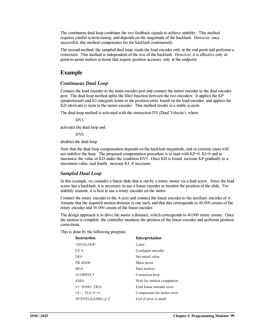
Continuous Dual Loop
Sampled Dual Loop
#DUALOOP
#END
Using the IT and VT Commands
Motion Smoothing
JP#CORRECT
Trapezoidal velocity and smooth velocity profiles
Homing
MG AT Home
#HOME
HM a
AM a
Home Switch
Input Function
Command Summary Homing Operation
High Speed Position Capture Latch
Operand Summary Homing Operation
AL B
This page Left Blank Intentionally
Global vs. Local Programming
Application Programming
ED #BEGIN
Edit Mode Commands
Entering Programs
Return
Invalid labels
Using Labels in Programs
Program Format
Valid labels
Commenting Programs
No Command and the Apostrophe ‘
Special Labels
Executing Programs Multitasking
REM Command
Debugging Programs
RAM Memory Interrogation Commands
Trace Command
Error Code Command
Stop Code Command
Eeprom Memory Interrogation Operands
Breakpoints and single stepping
Event Triggers & Trippoints
Program Flow Commands
AS a B C D E F G H
DMC-3425 Event Triggers
Example- Multiple Move Sequence
Example Start Motion on Input
Example- Set Output after Distance
Example- Repetitive Position Trigger
Example Multiple Move with Wait
Example Set Output when At Speed
Example Change Speed along Vector Path
Format
Example- Define Output Waveform Using AT
Command Format JP and JS
Conditional Jumps
Multiple Conditional Statements
Example using variables named V1, V2, V3
Logical operators
Conditional Statements
Examples
Using the if and Endif Commands
If, Else, and Endif
Format Description
Using the Else Command
Command Format IF, Else and Endif
Nesting if Conditional Statements
Stack Manipulation
Auto-Start and Auto Error Routine
Subroutines
Automatic Subroutines for Monitoring Conditions
Example Limit Switch
Example Position Error
Example Input Interrupt
Example Motion Complete Timeout
Example Command Error
Example Command Error w/Multitasking
Operator Function
Example Ethernet Communication Error
Mathematical and Functional Expressions
Mathematical Operators
LEN1=FLEN&$00FF
Bit-Wise Operators
ENTER,LENS6
FLEN=@FRACLEN
PR Posa
Variables
Functions
POS
Displaying the value of variables at the terminal
Programmable Variables
Assigning Values to Variables
Assigning Variable Values to Controller Parameters
Instruction
Example Using Variables for Joystick
Operands
Special Operands
Assignment of Array Entries
Arrays
Defining Arrays
Automatic Data Capture into Arrays
Using a Variable to Address Array Elements
Uploading and Downloading Arrays to On Board Memory
Example Recording into An Array
Command Summary Automatic Data Capture
Data Types for Recording
Operand Summary Automatic Data Capture
Specifying the Port for Messages
Outputting Numbers and Strings
Deallocating Array Space
Sending Messages
MG STR S3
Using the MG Command to Configure Terminals
Formatting Messages
Function Description
Displaying Variables and Arrays
Summary of Message Functions
Example Printing a Variable and an Array element
LZ1
Local Formatting of Response of Interrogation Commands
LZ0
V1=ALPHA
Formatting Variables and Array Elements
Local Formatting of Variables
VF1
Example- Set Bit and Clear Bit
Hardware I/O
Converting to User Units
Digital Outputs
Example- Output Port
Example Using Inputs to control program flow
Example Start Motion on Switch
Digital Inputs
Example Position Follower Point-to-Point
Input Interrupt Function
Analog Inputs
Example Position Follower Continuous Move
Configuring the I/O of the DMC-3425
Extended I/O of the DMC-3425 Controller
Bit I/O Block Binary Representation Decimal Value for
Accessing Extended I/O
Saving the State of the Outputs in Non-Volatile Memory
Argument Blocks Bits Description
Wire Cutter
Example Applications
Interfacing to Grayhill or OPTO-22 G4PB24
JP #A
X-Y Table Controller
BGC AMC
BGC
AMC
BGS AMS
Speed Control by Joystick
JG VEL JP #B
Position Control by Joystick
This page Left Blank Intentionally
Output Protection Lines
Hardware Protection
Programmable Position Limits
Signal or Function State if Error Occurs
Software Protection
Input Protection Lines
#AJP #AEN
Off-On-Error
Automatic Error Routine
Limit Switch Example
Limit Switch Routine
Symptom Cause Remedy
Installation
Operation
Symptom Cause
Communication
Stability
Theory of Operation
Level
Velocity and Position Profiles
Operation of Closed-Loop Systems
Functional Elements of a Motion Control System
System Modeling
Current Drive
Motor-Amplifier
Voltage Drive
Elements of velocity loops
Velocity Loop
Voltage Source
Digital Filter
DAC
ZOH
System Analysis
Motor Ms = P/I = Kt/Js2 = 500/s2 rad/A Amp Ka = 4 Amp/V
Analytical Method
System Design and Compensation
Kd = 10/32768 = Encoder Kf = 4N/2π =
DMC-3425 Theory of Operation
PID, T
Equivalent Filter Form
KP, KD, KI, PL
Servo Control
Electrical Specifications
Performance Specifications
Power Requirements
Acmdy Signa
Connectors for DMC-3425
J3 DMC-3425 General I/O 37- PIN D-type
Acmda Pwma
Signa
J3 DMC-3425-Stepper General I/O 37- PIN D-type
Pwmb
Signb Pwma
RTS CTS GND
Pin-Out Description
J1 RS232 Main port DB-9 Pin Male
DCD DTR GND DSR RTS CTS
ICM-1460 Interconnect Module
Features
Specifications
ACMDX/PULSEX
Reset
ERROR/PULSEY
AMPEN/SIGNY5
Opto-isolated inputs
Opto-Isolation Option for ICM-1460
Figure A-1
Opto-isolated outputs
CO n
Configuring the I/O of the DMC-3425 with DB-14064
Saving the State of the Outputs in Non-Volatile Memory
Accessing extended I/O
J6 50-PIN IDC Pin Signal Block Bit @INn Bit No @OUTn
Connector Description
Block Bit @INn Bit No @OUTn
Description
IOM-1964 Opto-Isolation Module for Extended I/O Controllers
Buffer chips
Overview
Figure A-4
Configuring Hardware Banks
Input Circuit
Figure A-6
High Power Digital Outputs
Standard Digital Outputs
Output Command Result
Standard Digital Outputs
Electrical Specifications
High Power Digital Outputs
Screw Terminal Listing
Relevant DMC Commands
DMC-3425 Appendices
PWROUT29
PWROUT32
PWROUT31
PWROUT30
1000 2000
Coordinated Motion Mathematical Analysis
Velocity
100000 = 0.05 s 2000000
WHO should Attend
List of Other Publications
Training Seminars
Galil Motion Control
Contacting Us
Warranty
Eeprom
Index
Homing, 38
Eeprom
Index DMC-3425