INSTALLATION
Mechanical installation
| 1 |
ON | OFF |
1
2 |
| 2 |
|
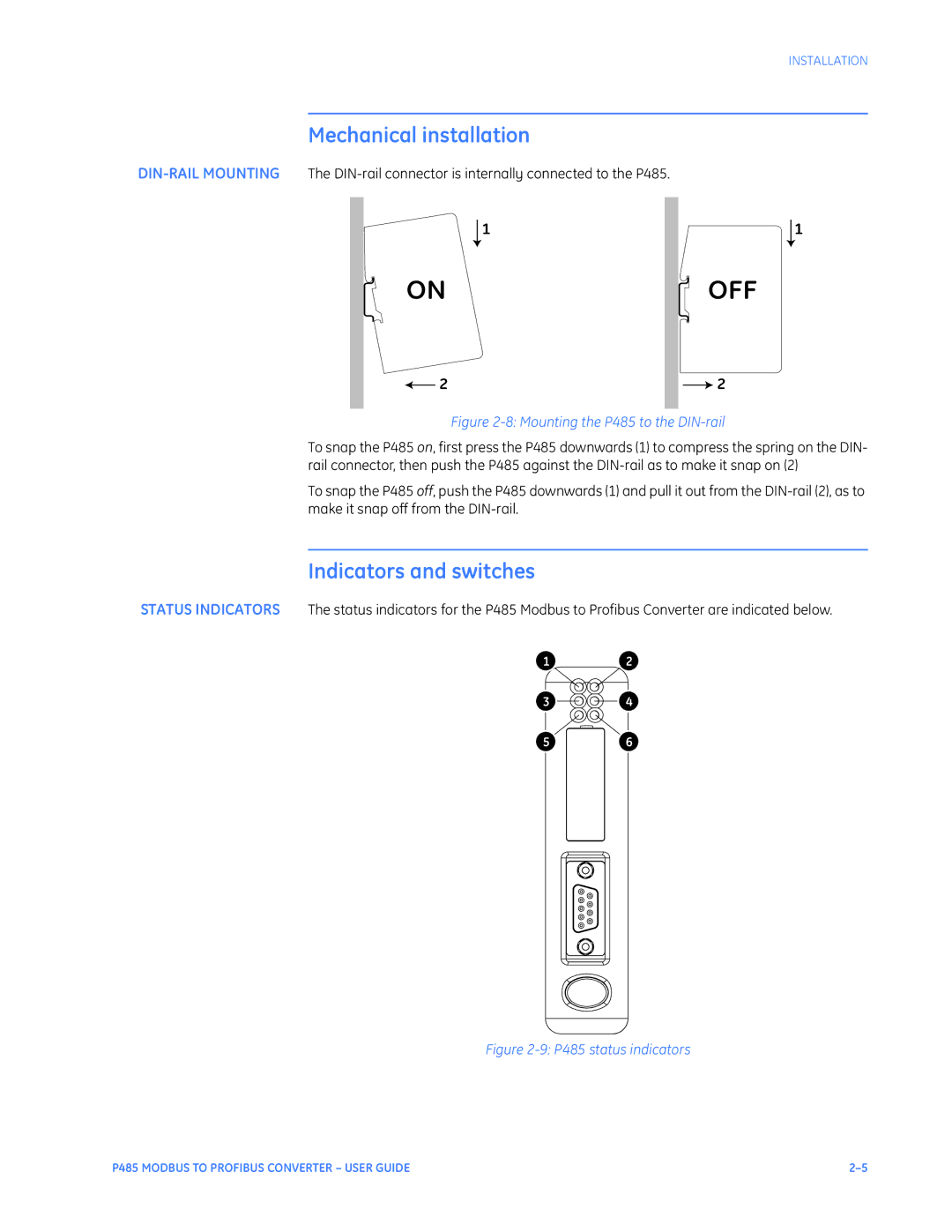
Figure 2-8: Mounting the P485 to the DIN-rail
To snap the P485 on, first press the P485 downwards (1) to compress the spring on the DIN- rail connector, then push the P485 against the
To snap the P485 off, push the P485 downwards (1) and pull it out from the
Indicators and switches
STATUS INDICATORS The status indicators for the P485 Modbus to Profibus Converter are indicated below.
1 2
3 4
5 6
Figure 2-9: P485 status indicators
P485 MODBUS TO PROFIBUS CONVERTER – USER GUIDE |