SOFTWARE OVERVIEW
Modbus network configuration
OVERVIEW When controlling a Modbus
See Input/output data during startup on page
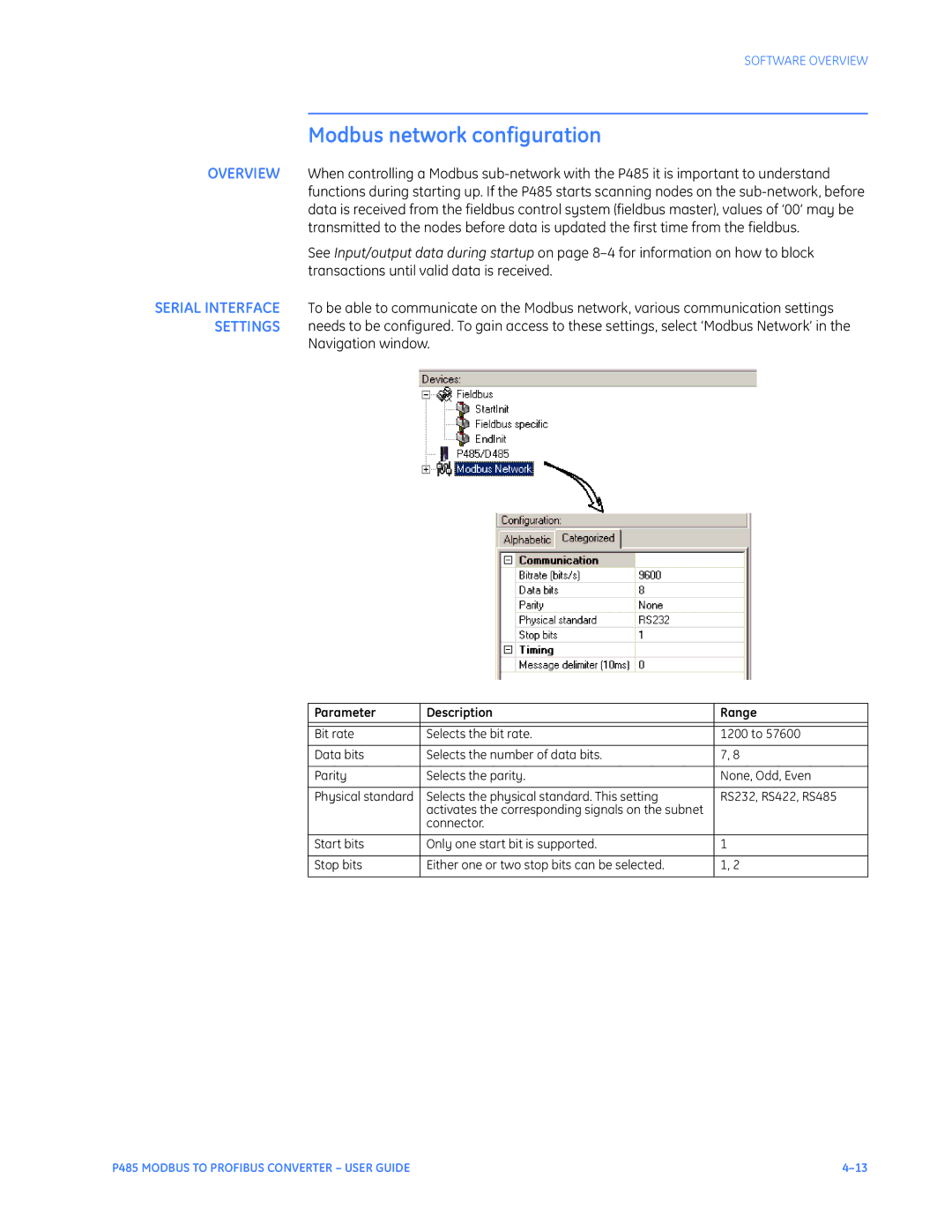
SERIAL INTERFACE To be able to communicate on the Modbus network, various communication settings SETTINGS needs to be configured. To gain access to these settings, select ‘Modbus Network’ in the
Navigation window.
Parameter | Description | Range |
|
|
|
Bit rate | Selects the bit rate. | 1200 to 57600 |
|
|
|
Data bits | Selects the number of data bits. | 7, 8 |
|
|
|
Parity | Selects the parity. | None, Odd, Even |
|
|
|
Physical standard | Selects the physical standard. This setting | RS232, RS422, RS485 |
| activates the corresponding signals on the subnet |
|
| connector. |
|
|
|
|
Start bits | Only one start bit is supported. | 1 |
|
|
|
Stop bits | Either one or two stop bits can be selected. | 1, 2 |
|
|
|
P485 MODBUS TO PROFIBUS CONVERTER – USER GUIDE |