DATA EXCHANGE
•Status register (0x0000 to 0x0001): If enabled, this register occupies the first two bytes in the input data area. For more information, see Control and status registers on page
•Input data area (0x002 to 0x00F3): This area holds data that should be sent to the fieldbus (see the status and control registers).
•Control register (0x0200 to 0x0201): If enabled, these register occupies the first two bytes in the output data area. For more information, see Control and status registers on page
•Output data area (0x200 to 0x2F3): This area holds data received from the fieldbus. Data cannot be written to this area.
•General data Area (0x0400 to 0x7FF): This data cannot be accessed from the fieldbus, and should be used for transfers between nodes on the
Protocol configuration
DESCRIPTION In order to be able to communicate on the Modbus
COMMUNICATION MODE The P485 supports the Modbus Master communication mode. In this mode, the P485 is setup to use the Modbus RTU protocol and implements a Modbus master for data exchange between the fieldbus and one or more devices on the
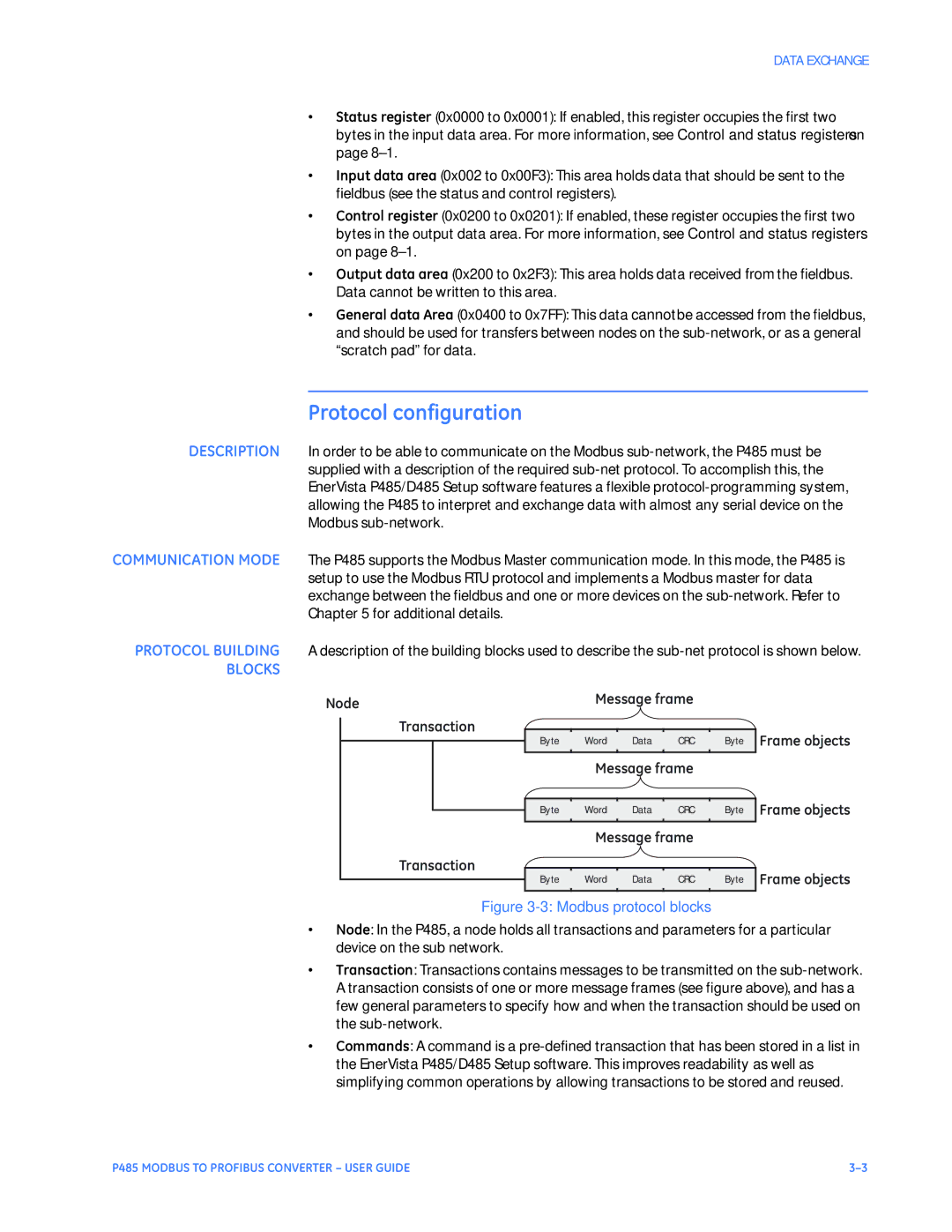
PROTOCOL BUILDING A description of the building blocks used to describe the
BLOCKS
Node | Message frame |
|
Transaction
Byte | Word | Data | CRC | Byte Frame objects |
Message frame
Transaction
Byte | Word | Data | CRC | Byte | Frame objects |
| Message frame |
|
| ||
|
|
|
|
| Frame objects |
Byte | Word | Data | CRC | Byte | |
|
|
|
|
|
|
Figure 3-3: Modbus protocol blocks
•Node: In the P485, a node holds all transactions and parameters for a particular device on the sub network.
•Transaction: Transactions contains messages to be transmitted on the
•Commands: A command is a
P485 MODBUS TO PROFIBUS CONVERTER – USER GUIDE |
