SOFTWARE OVERVIEW
•Parity: The parity can be selected as "Odd", "Even", or "None". This is a simple error check method capable of detecting single bit communication errors on a serial network (i.e. the
•Data bits: There can be "7" or "8" data bits. Generally, 8 data bits are used. This parameter determines how many bits per byte of user data that is transmitted on the
•Stop bits: There can be "1" or "2" stop bits. Determines the number of stop bits at the end of each byte sent on the
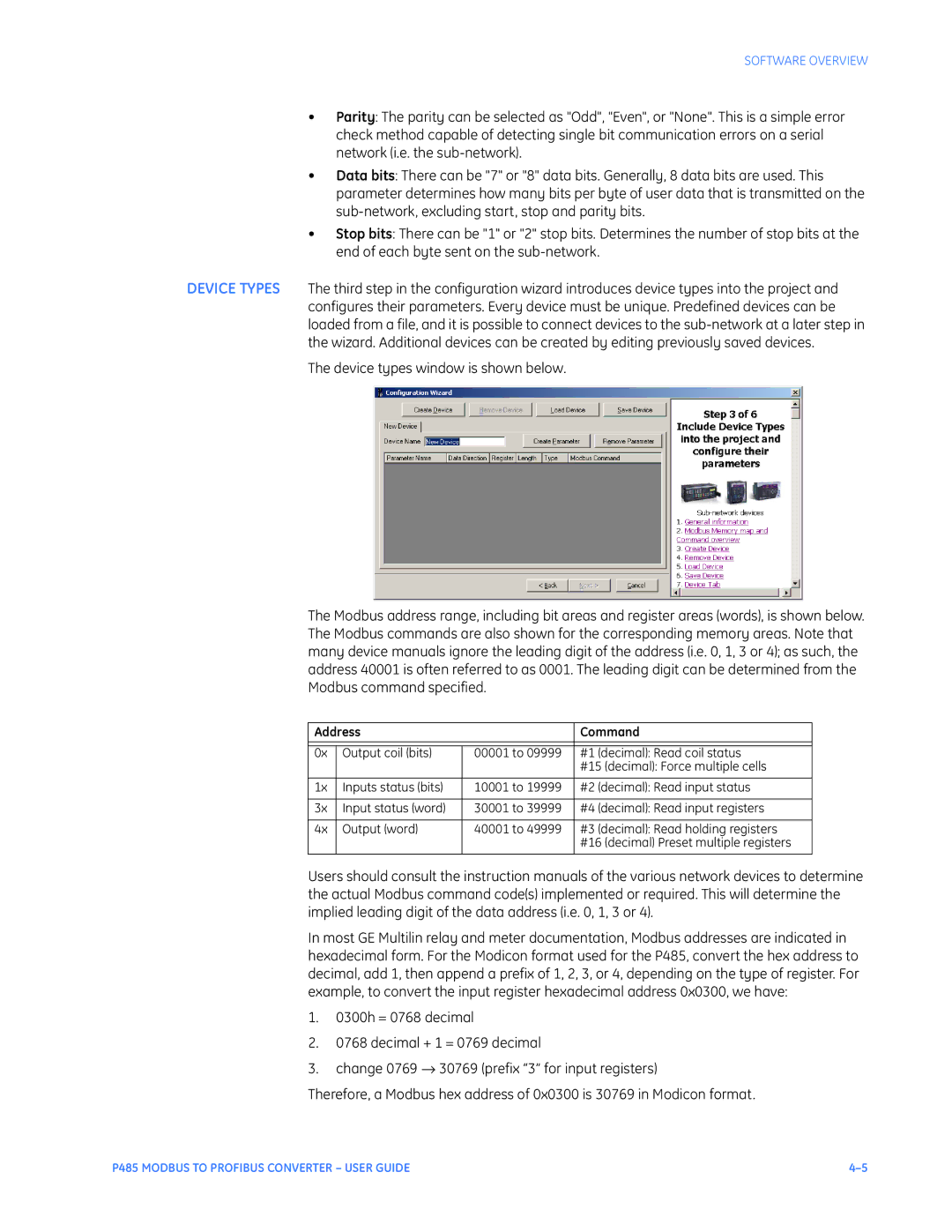
DEVICE TYPES The third step in the configuration wizard introduces device types into the project and configures their parameters. Every device must be unique. Predefined devices can be loaded from a file, and it is possible to connect devices to the
The device types window is shown below.
The Modbus address range, including bit areas and register areas (words), is shown below. The Modbus commands are also shown for the corresponding memory areas. Note that many device manuals ignore the leading digit of the address (i.e. 0, 1, 3 or 4); as such, the address 40001 is often referred to as 0001. The leading digit can be determined from the Modbus command specified.
Address |
| Command | |
|
|
|
|
0x | Output coil (bits) | 00001 to 09999 | #1 (decimal): Read coil status |
|
|
| #15 (decimal): Force multiple cells |
|
|
|
|
1x | Inputs status (bits) | 10001 to 19999 | #2 (decimal): Read input status |
|
|
|
|
3x | Input status (word) | 30001 to 39999 | #4 (decimal): Read input registers |
|
|
|
|
4x | Output (word) | 40001 to 49999 | #3 (decimal): Read holding registers |
|
|
| #16 (decimal) Preset multiple registers |
|
|
|
|
Users should consult the instruction manuals of the various network devices to determine the actual Modbus command code(s) implemented or required. This will determine the implied leading digit of the data address (i.e. 0, 1, 3 or 4).
In most GE Multilin relay and meter documentation, Modbus addresses are indicated in hexadecimal form. For the Modicon format used for the P485, convert the hex address to decimal, add 1, then append a prefix of 1, 2, 3, or 4, depending on the type of register. For example, to convert the input register hexadecimal address 0x0300, we have:
1.0300h = 0768 decimal
2.0768 decimal + 1 = 0769 decimal
3.change 0769 → 30769 (prefix “3” for input registers)
Therefore, a Modbus hex address of 0x0300 is 30769 in Modicon format.
P485 MODBUS TO PROFIBUS CONVERTER – USER GUIDE |