FRAME AND COMMAND EDITORS
SPECIFYING A NEW COMMAND
Select ‘Add Command’ as described earlier.
This example is taken from a Modbus RTU implementation, which means that the frame will always consist of one byte for slave address, one byte for function code and two bytes for CRC. Furthermore, each command always consists of a query and a response.
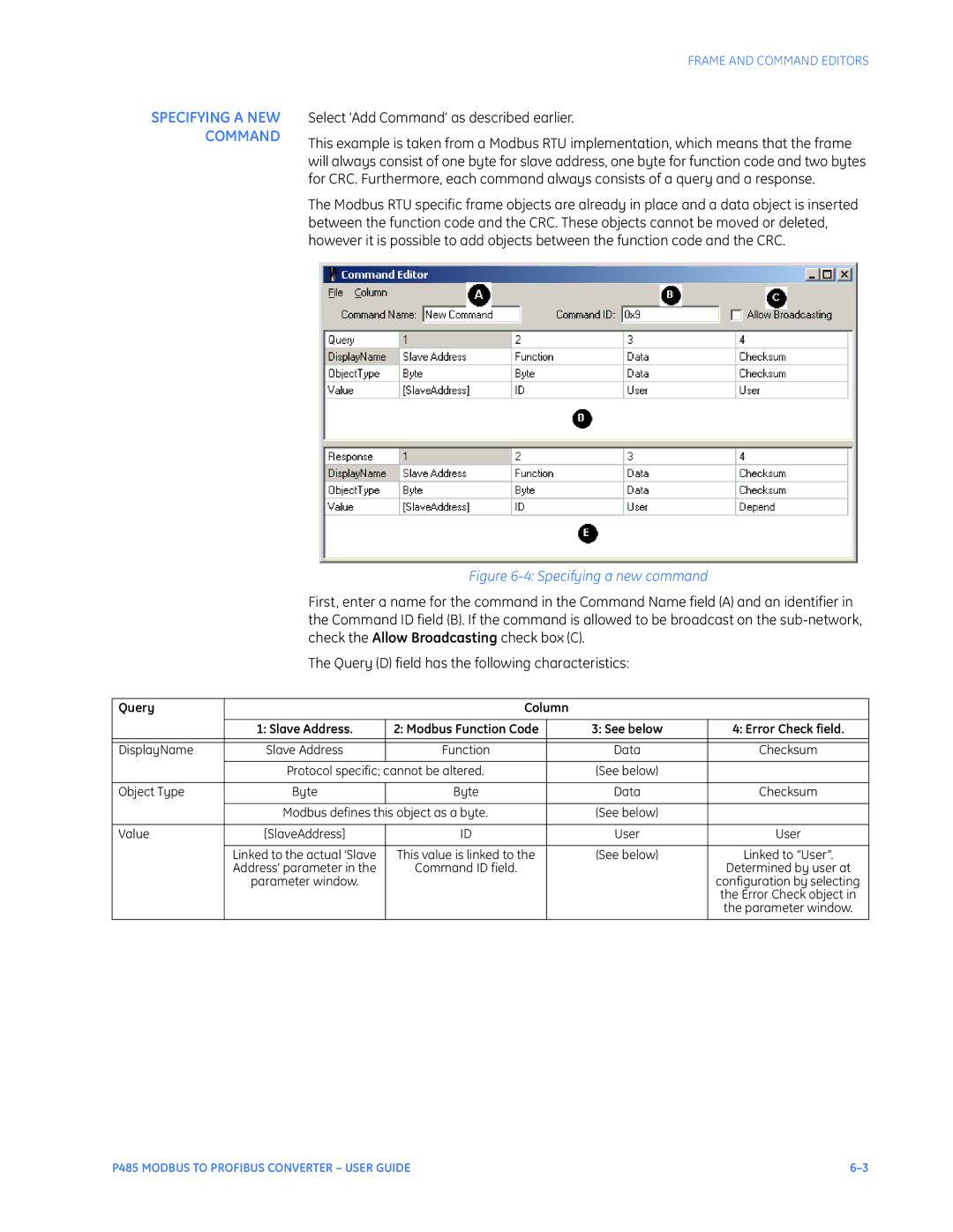
The Modbus RTU specific frame objects are already in place and a data object is inserted between the function code and the CRC. These objects cannot be moved or deleted, however it is possible to add objects between the function code and the CRC.
|
| Figure |
| ||
| First, enter a name for the command in the Command Name field (A) and an identifier in | ||||
| the Command ID field (B). If the command is allowed to be broadcast on the | ||||
| check the Allow Broadcasting check box (C). |
|
| ||
| The Query (D) field has the following characteristics: |
| |||
|
|
|
|
|
|
Query |
| Column |
|
| |
|
|
|
|
|
|
| 1: Slave Address. | 2: Modbus Function Code |
| 3: See below | 4: Error Check field. |
|
|
|
|
|
|
|
|
|
|
|
|
DisplayName | Slave Address | Function |
| Data | Checksum |
|
|
|
|
|
|
| Protocol specific; cannot be altered. |
| (See below) |
| |
|
|
|
|
|
|
Object Type | Byte | Byte |
| Data | Checksum |
|
|
|
|
|
|
| Modbus defines this object as a byte. |
| (See below) |
| |
|
|
|
|
|
|
Value | [SlaveAddress] | ID |
| User | User |
|
|
|
|
|
|
| Linked to the actual ‘Slave | This value is linked to the |
| (See below) | Linked to “User”. |
| Address’ parameter in the | Command ID field. |
|
| Determined by user at |
| parameter window. |
|
|
| configuration by selecting |
|
|
|
|
| the Error Check object in |
|
|
|
|
| the parameter window. |
|
|
|
|
|
|
P485 MODBUS TO PROFIBUS CONVERTER – USER GUIDE |
