APPLICATION EXAMPLE
SYSTEM SETUP This chapter describes how to set up the P485 with MM2 relay and PQMII meter to read and write parameters. It can also be used as a guideline to setup the P485 Modbus to Profibus Converter for communication with any GE Multilin relays.
The PQMII and MM2 devices are serially connected
•Read phase current Ia, Ib, and Ic actual values from memory locations 0240h to 0242h
•Read average current from memory location 0244h
•Read neutral current from memory location 0245h
•Read average phase voltage from memory location 0286h to 0287h
The following data is set up for the MM2:
•Read motor status from memory location 0023h
•Read switch input status from memory location 0010h
•Read motor load from memory location 0035h
•Read thermal capacity from memory location 0036h
•Read metered voltage from memory location 0040h
•The START A (command code 0x0005) and STOP (command code 0x0004) commands using Modbus function 10h: Preset multiple registers.
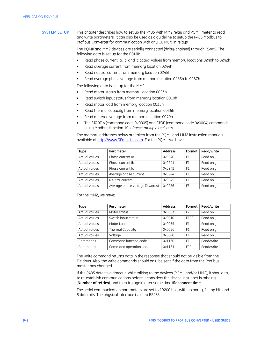
The memory addresses below are taken from the PQMII and MM2 instruction manuals available at http://www.GEmultilin.com. For the PQMII, we have:
Type | Parameter | Address | Format | Read/write |
|
|
|
|
|
Actual values | Phase current Ia | 0x0240 | F1 | Read only |
|
|
|
|
|
Actual values | Phase current Ib | 0x0241 | F1 | Read only |
|
|
|
|
|
Actual values | Phase current Ic | 0x0242 | F1 | Read only |
|
|
|
|
|
Actual values | Average phase current | 0x0244 | F1 | Read only |
|
|
|
|
|
Actual values | Neutral current | 0x0245 | F1 | Read only |
|
|
|
|
|
Actual values | Average phase voltage (2 words) | 0x0286 | F3 | Read only |
|
|
|
|
|
For the MM2, we have: |
|
|
| |
Type | Parameter | Address | Format | Read/write |
|
|
|
|
|
Actual values | Motor status | 0x0023 | F7 | Read only |
|
|
|
|
|
Actual values | Switch input status | 0x0010 | F100 | Read only |
|
|
|
|
|
Actual values | Motor Load | 0x0035 | F1 | Read only |
|
|
|
|
|
Actual values | Thermal Capacity | 0x0036 | F1 | Read only |
|
|
|
|
|
Actual values | Voltage | 0x0040 | F1 | Read only |
|
|
|
|
|
Commands | Command function code | 0x1160 | F1 | Read/write |
|
|
|
|
|
Commands | Command operation code | 0x1161 | F22 | Read/write |
|
|
|
|
|
The write command returns data in the response that should not be visible from the Fieldbus. Also, the write commands should only be sent if the data from the Profibus master has changed.
If the P485 detects a timeout while talking to the devices (PQMII and/or MM2), it should try to
The serial communication parameters are set to 19200 bps, with no parity, 1 stop bit, and 8 data bits. The physical interface is set to RS485.
P485 MODBUS TO PROFIBUS CONVERTER – USER GUIDE |
