ADVANCED FUNCTIONS
Input/output data during startup
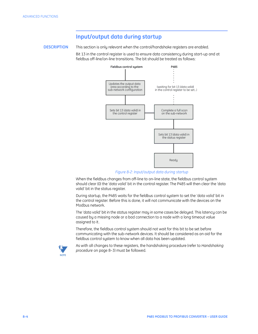
DESCRIPTION This section is only relevant when the control/handshake registers are enabled.
Bit 13 in the control register is used to ensure data consistency during
Fieldbus control system | P485 |
Updates the output data area according to the
(waiting for bit 13 (data valid) in the control register to be set...)
Sets bit 13 (data valid) in the control register
Complete a full scan on the
Sets bit 13 (data valid) in
the status register
Ready
Figure 8-2: Input/output data during startup
When the fieldbus changes from
During startup, the P485 waits for the fieldbus control system to set the ‘data valid’ bit in the control register. Before this is done, it will not communicate with the devices on the Modbus network.
The ‘data valid’ bit in the status register may in some cases be delayed. This latency can be caused by a missing node or a bad connection to a node with a long timeout value assigned to it.
Therefore, the fieldbus control system should not wait for this bit to be set before communicating with the
As with all changes to these registers, the handshaking procedure (refer to Handshaking procedure on page
NOTE
P485 MODBUS TO PROFIBUS CONVERTER – USER GUIDE |