SOFTWARE OVERVIEW
P485/D485 configuration
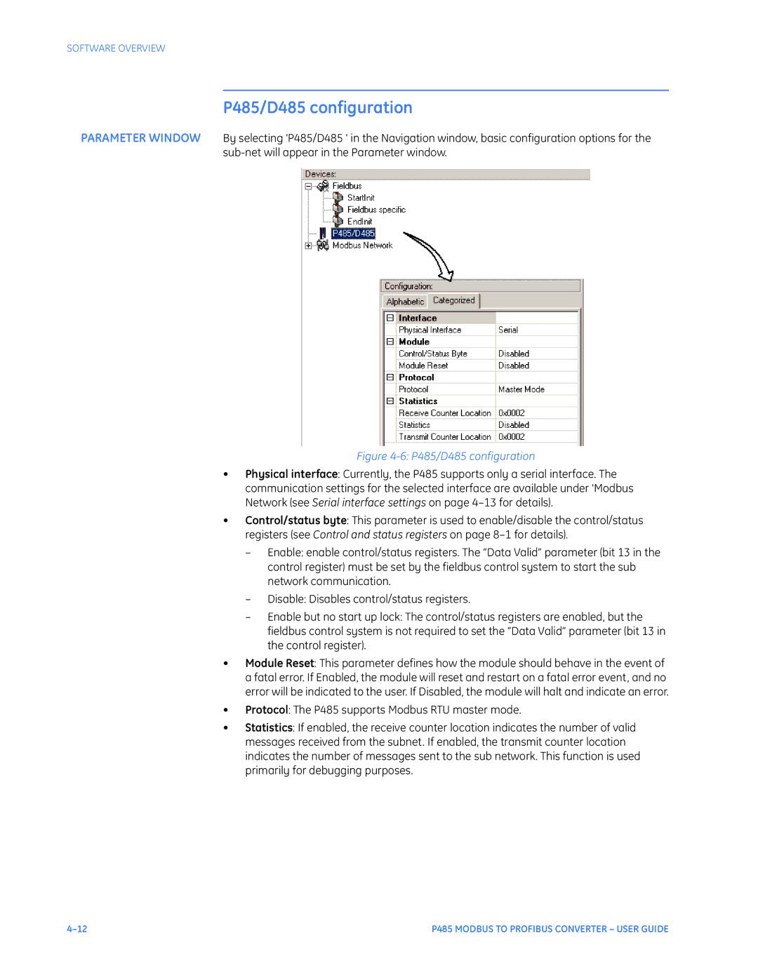
PARAMETER WINDOW By selecting 'P485/D485 ' in the Navigation window, basic configuration options for the
Figure 4-6: P485/D485 configuration
•Physical interface: Currently, the P485 supports only a serial interface. The communication settings for the selected interface are available under 'Modbus Network (see Serial interface settings on page
•Control/status byte: This parameter is used to enable/disable the control/status registers (see Control and status registers on page
–Enable: enable control/status registers. The “Data Valid” parameter (bit 13 in the control register) must be set by the fieldbus control system to start the sub network communication.
–Disable: Disables control/status registers.
–Enable but no start up lock: The control/status registers are enabled, but the fieldbus control system is not required to set the “Data Valid” parameter (bit 13 in the control register).
•Module Reset: This parameter defines how the module should behave in the event of a fatal error. If Enabled, the module will reset and restart on a fatal error event, and no error will be indicated to the user. If Disabled, the module will halt and indicate an error.
•Protocol: The P485 supports Modbus RTU master mode.
•Statistics: If enabled, the receive counter location indicates the number of valid messages received from the subnet. If enabled, the transmit counter location indicates the number of messages sent to the sub network. This function is used primarily for debugging purposes.
P485 MODBUS TO PROFIBUS CONVERTER – USER GUIDE |