FRAME AND COMMAND EDITORS
This command will allocate two bytes of output data in the OUT area and no swapping will occur. The data is followed by a
The same steps are required for the response frame. If the response holds data, it should be allocated in the input area that starts at address 0x002. To apply the changes, select File > Apply Changes. To exit without saving, select File > Exit.
Command editor
GENERAL The command editor makes it possible to add custom commands to the P485.
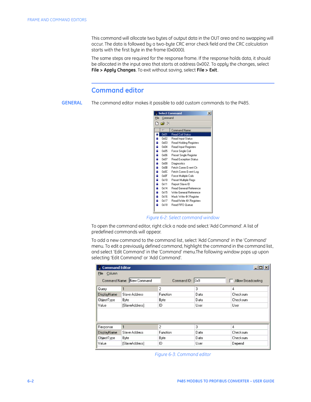
Figure 6-2: Select command window
To open the command editor, right click a node and select ‘Add Command’. A list of predefined commands will appear.
To add a new command to the command list, select ‘Add Command’ in the ‘Command’ menu. To edit a previously defined command, highlight the command in the command list, and select ‘Edit Command’ in the ‘Command’ menu.The following window pops up upon selecting ‘Edit Command’ or ‘Add Command’.
Figure 6-3: Command editor
P485 MODBUS TO PROFIBUS CONVERTER – USER GUIDE |